Chevrolet Trax: Knock sensor system description
Circuit/System Description
The knock sensor system enables the engine control module (ECM) to control the ignition timing for the best possible performance while protecting the engine from potentially damaging levels of detonation. The ECM uses the knock sensor system to test for abnormal engine noise that may indicate detonation, also known as spark knock.
Sensor Description
The knock sensor system uses a flat response sensor. The sensor uses a piezo-electric crystal technology that produces an AC voltage signal of varying amplitude and frequency based on the engine vibration or noise level.
The amplitude and frequency are dependant upon the level of knock that the knock sensor detects. The knock sensor is connected to the engine control module (ECM) by a signal circuit and a low reference circuit. Both knock sensor circuits are protected from electromagnetic interference by a shielding ground circuit. The shielding ground circuit is grounded through the ECM.
The ECM learns a minimum noise level, or back ground noise, at idle from the knock sensor and uses calibrated values for the rest of the engine speed range. The control module uses the minimum noise level to calculate a noise channel. A normal knock sensor signal is within the noise channel. As engine speed and load changes, the noise channel upper and lower parameters change to accommodate the normal knock sensor signal, keeping the signal within the channel. In order to determine which cylinders are knocking, the ECM only uses knock sensor signal information when each cylinder is near top dead center of the firing stroke. If knock is present, the ECM detects that the signal is outside of the noise channel.
If the ECM detects that knock is present, the ECM retards the ignition timing to attempt to eliminate the knock.
The ECM always attempts to adjust back to a zero compensation level, or no spark retard. An abnormal knock sensor signal stays outside of the noise channel or will not be present. Knock sensors diagnostics are calibrated to detect faults with the knock sensor circuitry inside the ECM, the knock sensor wiring, or the knock sensor voltage output. Some diagnostics are also calibrated to detect constant noise from an outside influence such as a loose, damaged component, or excessive engine mechanical noise.
THROTTLE ACTUATOR CONTROL (TAC) SYSTEM DESCRIPTION
.gif)
Fig. 3: Throttle Actuator Control (TAC) System
The engine control module (ECM) is the control center for the throttle actuator control (TAC) system. The ECM determines the driver's intent based on input from the accelerator pedal position sensors, then calculates the appropriate throttle response based on the throttle position sensors. The ECM achieves throttle positioning by providing a pulse width modulated voltage to the throttle actuator motor. The throttle blade is spring loaded in both directions, and the default position is slightly open.
Modes Of Operation
Normal Mode
During the operation of the TAC system, several modes, or functions, are considered normal. The following modes may be entered during normal operations:
- Minimum pedal value-At key-up, the ECM updates the learned minimum pedal value.
- Minimum throttle position values-At key-up, the ECM updates the learned minimum throttle position value. In order to learn the minimum throttle position value, the throttle blade is moved to the Closed position.
- Ice break mode-If the throttle blade is not able to reach a predetermined minimum throttle position, the ice break mode is entered. During the ice break mode, the ECM commands the maximum pulse width several times to the throttle actuator motor in the closing direction.
- Minimum pedal value-At key-up, the ECM updates the learned minimum pedal value.
- Battery saver mode-After a predetermined time without engine RPM, the ECM commands the Battery Saver mode. During the Battery Saver mode, the TAC module removes the voltage from the motor control circuits, which removes the current draw used to maintain the idle position and allows the throttle to return to the spring loaded default position.
Reduced Engine Power Mode
When the ECM detects a condition with the TAC system, the ECM may enter a reduced engine power mode.
Reduced engine power may cause one or more of the following conditions:
- Acceleration limiting-The ECM will continue to use the accelerator pedal for throttle control, however, the vehicle acceleration is limited.
- Limited throttle mode-The ECM will continue to use the accelerator pedal for throttle control, however, the maximum throttle opening is limited.
- Throttle default mode-The ECM will turn OFF the throttle actuator motor, and the throttle will return to the spring loaded default position.
- Forced idle mode-The ECM will perform the following actions:
- Limit engine speed to idle positioning the throttle position, or by controlling the fuel and spark if the throttle is turned OFF.
- Ignore the accelerator pedal input.
- Engine shutdown mode-The ECM will disable fuel and de-energize the throttle actuator
TURBOCHARGER SYSTEM DESCRIPTION
.gif)
Fig. 4: Turbocharger System Description Diagram
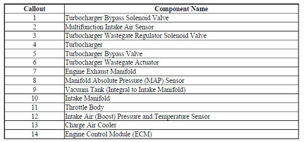
Turbocharger Description and Operation
A turbocharger is a forced induction device used for increasing power output of an internal combustion engine.
By using the exhaust gas forces to compress intake air, a turbocharged engine is more powerful and efficient than a naturally aspirated engine with the same displacement. The dual-scroll turbocharger is mounted on the exhaust manifold and the lightweight turbine is driven by the waste energy generated by the flow of the exhaust gases. The turbine is connected by a shaft to the compressor which is mounted in the induction system of the engine. The compressor vanes compress the intake air above atmospheric pressure, thereby greatly increasing the density of the air entering the engine.
The turbocharger incorporates a wastegate that is controlled by the ECM, by means of a pulse width modulated (PWM) solenoid, to regulate the pressure ratio of the compressor. An integral turbocharger bypass valve, controlled by the ECM through a remotely mounted solenoid, is used to prevent compressor surging and damage by opening during abrupt closed throttle conditions. The bypass valve opens during closed throttle deceleration conditions, which allows the air to recirculate in the turbocharger and maintain compressor speed.
During a wide open throttle command, the bypass valve closes to optimize turbo response.
The turbocharger is connected to the engine oiling system by a supply and drain tube and synthetic oil is installed at the factory. Synthetic oil is required for its friction-reducing capabilities and high-temperature performance. There is a cooling system circuit in the turbocharger that utilizes the engine coolant to further reduce operating temperatures.
Turbocharger Wastegate Solenoid Valve
The wastegate valve opens and closes a bypass passage beside the turbine wheel. A spiral spring works in the closing direction while the pressure in the diaphragm works in the opening direction. The ECM supplies a PWM signal to the solenoid valve, which then allows pressure from the turbo to come through. When the pressure overcomes the spring force the actuator rod begins to move, opening the wastegate valve to a corresponding degree. The ECM changes wastegate valve opening by varying the PWM signal, which regulates the turbine speed.
At low loads, the wastegate valve is closed. All the exhaust gas then passes through the turbine. At high loads, the volume of exhaust gas is greater, which makes the turbine wheel rotate faster. This delivers a greater air displacement to the engine.
When the air displacement becomes so large that the current air mass per combustion cannot be controlled with the throttle alone, the turbo must be regulated. This is done by opening the wastegate valve so that some of the exhaust gas passes through the wastegate. Consequently, this gas does not contribute to driving the turbine and the turbine speed will be regulated so that the turbo air displacement will be correct.
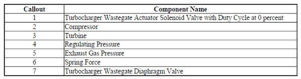
When certain DTCs are set the ECM will limit the amount of available boost pressure. Limiting boost pressure is accomplished by the ECM controlling the wastegate actuator solenoid valve and maintaining the duty cycle at 0 %. This means that the ECM will not actively close the wastegate during greater engine loads. The system at this point is limited to mechanical boost. Mechanical boost means that the wastegate will still move, but the amount of motion is limited by the mechanical properties of the return spring within the diaphragm valve, the pneumatic properties of the actuator, and the physics of the exhaust gas flow in the exhaust system.
The turbocharger wastegate diaphragm valve assembly has a threaded rod and nut that connects the diaphragm of the valve to the wastegate. This rod is adjusted to factory specifications and is not adjustable.
The following diagrams illustrate the turbocharger wastegate closed and open conditions:
Turbocharger Wastegate Closed
.gif)
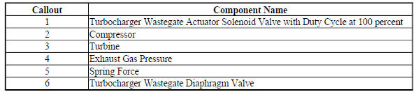
Fig. 5: TC Wastegate Closed
Turbocharger Wastegate Open
.gif)
Fig. 6: TC Wastegate Open
The wastegate is completely closed at idle. All of the exhaust energy is passing through the turbine.
During normal operation, when wide open throttle is requested at lower engine speeds, the ECM commands the wastegate solenoid with a duty cycle of 100 % to minimize any turbo lag. During engine loads in the middle and upper RPM ranges, the ECM commands the solenoid with a duty cycle of about 65 %.
Turbocharger Bypass Solenoid Valve
The turbocharger bypass valve prevents the turbo from exceeding the pump limit at low flow and high pressure.
This occurs when the engine is running with a load and the throttle suddenly closes. In this case, flow is almost null and pressure is very high. This not only is damaging to the turbocharger, but also generates noise and decelerates turbine speed. The ECM supplies a voltage signal to the solenoid valve output driver, which regulates the open or closed valve position.
Accelerator Pedal Depressed
The bypass valve is closed. The force in the return spring integrated in the valve presses the valve cone against its seat in the turbo housing. The valve is turned OFF.
Accelerator Pedal Released
In order to avoid pressure spikes in the intake manifold and unloading or overrunning the turbo, the ECM sends a voltage signal to the bypass valve, which will then open. The compressed air on the pressure side of the turbo is led to the intake via the open valve. When the pressure drops, the turbine speed can be kept relatively high and the turbocharger is prevented from exceeding the pump limit.
Charge Air Cooler
The turbocharger is supported by an air-to-air charge air cooler system, which uses fresh air drawn through a heat exchanger to reduce the temperature of the warmer compressed air forced through the intake system. Inlet air temperature can be reduced by up to 100ºC (180ºF), which enhances performance. This is due to the higher density of oxygen in the cooled air, which promotes optimal combustion. The charge air cooler is connected to the turbocharger and to the throttle body by flexible ductwork that requires the use of special high torque fastening clamps. In order to prevent any type of air leak when servicing the ductwork, the tightening specifications and proper positioning of the clamps is critical, and must be strictly adhered to.
READ NEXT:
 DTC P0010, P0013, OR P2088-P2091
Diagnostic Instructions
Perform the Diagnostic System Check - Vehicle prior to using this
diagnostic procedure.
Review Strategy Based Diagnosis for an overview of the diagnostic
approach.
Diag
DTC P0011 OR P0014
Diagnostic Instructions
Perform the Diagnostic System Check - Vehicle prior to using this
diagnostic procedure.
Review Strategy Based Diagnosis for an overview of the diagnostic
approach.
Diag
SEE MORE:
Brake fluid
The purpose of brake fluid is to:
Utilize hydraulic pressure to apply force on brake components that use a
friction material to slow the
vehicle
Protect the brake system from corrosion
Motor vehicle brake fluids are hygroscopic and absorb moisture when exposed
to the atmosphere and in servic
Rear compartment floor panel replacement
Removal Procedure
WARNING: Refer to Approved Equipment for Collision Repair Warning .
WARNING: Refer to Glass and Sheet Metal Handling Warning .
Disable the SIR system. Refer to SIR Disabling and Enabling .
Disconnect the negative battery cable. Refer to Battery Negative Cable
Disconnection and
