Chevrolet Trax: DTC P0010, P0013, OR P2088-P2091
Diagnostic Instructions
- Perform the Diagnostic System Check - Vehicle prior to using this diagnostic procedure.
- Review Strategy Based Diagnosis for an overview of the diagnostic approach.
- Diagnostic Procedure Instructions provides an overview of each diagnostic category
DTC Descriptor
DTC P0010
Intake Camshaft Position Actuator Solenoid Valve Control Circuit
DTC P0013
Exhaust Camshaft Position Actuator Solenoid Valve Control Circuit
DTC P2088
Intake Camshaft Position Actuator Solenoid Valve Control Circuit High Voltage
DTC P2089
Intake Camshaft Position Actuator Solenoid Valve Control Circuit High Voltage
DTC P2090
Exhaust Camshaft Position Actuator Solenoid Valve Control Circuit Low Voltage
DTC P2091
Exhaust Camshaft Position Actuator Solenoid Valve Control Circuit High Voltage
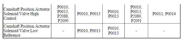
Diagnostic Fault Information
Circuit/System Description
The camshaft position actuator system enables the Engine Control Module (ECM) to change the timing of the camshafts while the engine is operating. The Camshaft Position Actuator Solenoid Valve signal from the ECM is pulse width modulated (PWM). The ECM controls the Camshaft Position Actuator Solenoid Valve duty cycle by controlling the amount of solenoid valve On time. The Camshaft Position Actuator Solenoid Valve controls the advance or the retard of each camshaft. The Camshaft Position Actuator Solenoid Valve controls the oil flow that applies the pressure to advance or retard the camshafts.
The ECM controls the Camshaft Position Actuator Solenoid Valve by suppling a 12 V pulse width modulated (PWM) signal. The ECM supplies a ground to the low reference circuit.
Conditions for Running the DTC
- The ignition voltage is greater than 11 V
- The ignition switch is in the crank or run position.
- The ECM has commanded the Camshaft Position Actuator Solenoid Valve On.
- The DTCs run continuously once the above conditions are met.
Conditions for Setting the DTC
The ECM detects that the commanded state of the driver and the actual state of the control circuit do not match for greater than 5 s.
Action Taken When the DTC Sets
DTCs P0010, P0013, P2088, P2089, P2090 and P2091 are type B DTCs.
Conditions for Clearing the DTC
DTCs P0010, P0013, P2088, P2089, P2090 and P2091 are type B DTCs.
Diagnostic Aids
If the condition is intermittent, move the related harnesses and connectors, with the engine operating, while monitoring the scan tool Circuit Test Status parameters for the component. The Circuit Test Status parameters change from OK or Not Run to Malfunction if there is a condition with the circuit or a connection.
Reference Information
Schematic Reference
Engine Controls Schematics (Encore) , Engine Controls Schematics (Trax)
Connector End View Reference
WIRING SYSTEMS AND POWER MANAGEMENT - COMPONENT CONNECTOR END VIEWS - INDEX - ENCORE WIRING SYSTEMS AND POWER MANAGEMENT - COMPONENT CONNECTOR END VIEWS - INDEX - TRAX
Component View Reference
Powertrain Component Views
Description and Operation
Camshaft Actuator System Description
Electrical Information Reference
- Circuit Testing
- Connector Repairs
- Testing for Intermittent Conditions and Poor Connections
- Wiring Repairs
DTC Type Reference
Powertrain Diagnostic Trouble Code (DTC) Type Definitions (LUV) , Powertrain Diagnostic Trouble Code (DTC) Type Definitions (2H0)
Scan Tool Reference
Control Module References for scan tool information
Circuit/System Verification
NOTE: If a crankshaft or camshaft position sensor DTC is set, the Camshaft Position Actuator output control will not function.
- Ignition On.
- Verify DTC P0335, P0336, P0340, or P0341 is not set.
- If any of the DTCs are set
Refer to Diagnostic Trouble Code (DTC) List - Vehicle .
- If none of the DTCs are set
- Engine idling, command the Camshaft Position Actuator to 10º while observing the following control circuit status parameters with a scan tool:
- Exhaust or Intake Camshaft Position Actuator Solenoid Valve Control Circuit Open Test Status
- Exhaust or Intake Camshaft Position Actuator Solenoid Valve Control Circuit Low Voltage Test Status
- Intake or Exhaust Camshaft Position Actuator Solenoid Valve Control Circuit High Voltage Test Status
- If Malfunction is displayed
Refer to Circuit/System Testing
- If Malfunction is not displayed
- Operate the vehicle within the Conditions for Running the DTC. You may also operate the vehicle within the conditions that you observed from the Freeze Frame/Failure Records data.
- Verify the DTC does not set.
- If the DTC sets
Refer to Circuit/System Testing.
- If the DTC does not set
- All OK.
Circuit/System Testing
- Ignition Off and all vehicle systems Off, disconnect the appropriate harness connector at the camshaft position actuator solenoid valve. It may take up to 2 minutes for all vehicle systems to power down.
- Test for less than 5 ohms between the low reference circuit terminal 1 and ground.
- If 5 ohms or greater
- Ignition Off, disconnect the harness connector at the K20 Engine Control Module.
- Test for less than 2 ohms in the low reference circuit end to end.
- If 2 ohms or greater, repair the open/high resistance in the circuit.
- If less than 2 ohms, replace the K20 Engine Control Module.
- If less than 5 ohms
- Test for less than 5 ohms between the control circuit terminal 2 and ground.
- If 5 ohms or greater
- Ignition Off, disconnect the harness connector at the K20 Engine Control Module.
- Test for less than 2 ohms in the control circuit end to end.
- If 2 ohms or greater, repair the open/high resistance in the circuit.
- If less than 2 ohms, replace the K20 Engine Control Module.
- If less than 5 ohms
- Ignition On.
NOTE: A test lamp must be used for this test. The control circuit is pulled-up to a low current voltage, 1.5-3.5 V on the control circuit is normal.
- Verify that a test lamp does not illuminate between the control circuit terminal 2 and ground.
- If the test lamp illuminates
- Ignition Off, disconnect the harness connector at the K20 Engine Control Module, ignition On.
- Test for less than 1 V between the control circuit and ground.
- If 1 V or greater, repair the short to voltage on the circuit
- If less than 1 V, replace the K20 Engine Control Module
- If the test lamp does not illuminate
- Remove the test lamp.
- Connect the DMM black lead to the control circuit terminal 2. Connect the DMM red lead to B+. Set the DMM on the diode setting. Command the CMP actuator solenoid On and Off with a scan tool. The DMM should transition from OL when commanded Off to less than 1 V when commanded On.
- If the circuit voltage does not correspond to the specified values
- Ignition Off, disconnect the harness connector at the K20 Engine Control Module.
- Test for less than 2 ohms in the control circuit end to end.
- If 2 ohms or greater, repair the open/high resistance or short to ground in the circuit
- If less than 2 ohms, replace the K20 Engine Control Module
- If the circuit voltage corresponds to the specified values
- Test or replace the appropriate camshaft position actuator solenoid valve.
Component Testing
- Ignition Off, disconnect the harness connector at the appropriate Q6 Camshaft Position Actuator Solenoid Valve.
- Test for 7-12 ohms between the control terminal 2 and the low reference circuit terminal 1.
- If not between 7-12 ohms
Replace the Q6 Camshaft Position Actuator Solenoid Valve.
- If between 7-12 ohms
- Test for infinite resistance between each terminal and the Q6 Camshaft Position Actuator Solenoid Valve housing
- If less than infinite resistance
Replace the Q6 Camshaft Position Actuator Solenoid Valve.
- If infinite resistance
- All OK.
Repair Instructions
Perform the Diagnostic Repair Verification after completing the repair.
- Camshaft Position Actuator Solenoid Valve Replacement
- Control Module References for Engine Control Module replacement, programming and setup.
READ NEXT:
 DTC P0011 OR P0014
Diagnostic Instructions
Perform the Diagnostic System Check - Vehicle prior to using this
diagnostic procedure.
Review Strategy Based Diagnosis for an overview of the diagnostic
approach.
Diag
DTC P0016 OR P0017
Diagnostic Instructions
Perform the Diagnostic System Check - Vehicle prior to using this
diagnostic procedure.
Review Strategy Based Diagnosis for an overview of the diagnostic
approach.
Diag
DTC P0030-P0032, P0036-P0038, P0053, P0054, P0135, OR P0141
Diagnostic Instructions
Perform the Diagnostic System Check - Vehicle prior to using this
diagnostic procedure.
Review Strategy Based Diagnosis for an overview of the diagnostic
approach.
Diag
SEE MORE:
Bluetooth malfunction (onstar)
Diagnostic Instructions
Perform the Diagnostic System Check - Vehicle prior to using this
diagnostic procedure.
Review Strategy Based Diagnosis for an overview of the diagnostic
approach.
Diagnostic Procedure Instructions provide an overview of each diagnostic
category.
Circuit/System Des
Automotive terminology & definitions
ACTIVE SUSPENSION SYSTEM
active suspension systems move each wheel up and down to control body motion
in response to road
abnormalities. The system responds to inputs from the road and the driver. With
an active suspension, a
vehicle can simultaneously provide the smooth ride of a soft suspension
