Chevrolet Trax: Instrument panel assembly replacement (trax)
Removal Procedure
- Disable the SIR system. Refer to SIR Disabling and Enabling .
.gif)
Fig. 30: Windshield Garnish Molding Assembly
- Remove both of the windshield garnish moldings (1). Refer to Windshield Garnish Molding Replacement (Trax) .
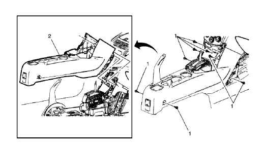
Fig. 31: Front Floor Console
- Remove the front floor console (2). Refer to Front Floor Console Replacement (Trax).
.gif)
Fig. 32: Front Floor Console Stowage Tray
- Remove the front floor console stowage tray (2). Refer to Front Floor Console Stowage Tray Replacement (Trax).
.gif)
Fig. 33: Instrument Panel Outer Trim Covers
- Remove the instrument panel outer trim covers (1) left side and (2) right side. Refer to Instrument Panel Outer Trim Cover Replacement (Trax).
.gif)
Fig. 34: Instrument Panel Upper Center Compartment
- Remove the instrument panel upper center compartment (3). Refer to Instrument Panel Upper Center Compartment Replacement.
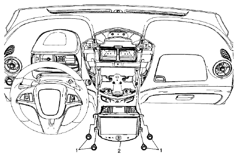
Fig. 35: Radio
- Remove the radio (2). Refer to Radio Replacement (Encore) , Radio Replacement (Trax) .
.gif)
Fig. 36: Instrument Panel Lower Center Trim Plate Applique
- Remove the instrument panel lower center trim plate applique (2). Refer to Instrument Panel Lower Center Trim Plate Applique Replacement (Trax).
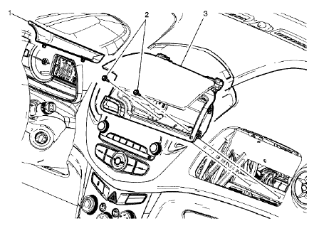
Fig. 37: Instrument Panel Upper Compartment
- Remove the instrument panel upper compartment (3). Refer to Instrument Panel Upper Compartment Replacement (Trax).
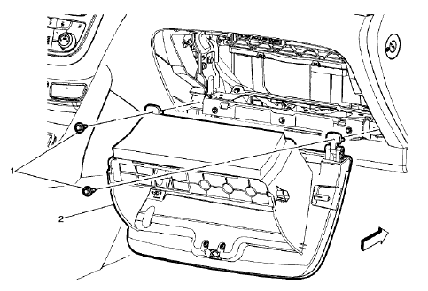
Fig. 38: Instrument Panel Compartment
- Remove the instrument panel compartment (2). Refer to Instrument Panel Compartment Replacement.
.gif)
Fig. 39: Instrument Panel Outer Air Outlet
- Remove the instrument panel outer air outlets (1) left side and (2) right side. Refer to Instrument Panel Outer Air Outlet Replacement (Trax) .
.gif)
Fig. 40: Steering Column Upper Support Bracket
- Remove the steering column. Refer to Steering Column Replacement (Mexico, N40) , Steering Column Replacement (Canada, NJ1) , Steering Column Replacement (United States, NJ1) .
.gif)
Fig. 41: Instrument Cluster
- Remove the instrument cluster (2). Refer to Instrument Cluster Replacement (Trax) .
.gif)
Fig. 42: Headlamp Switch
- Remove the headlamp switch (1). Refer to Headlamp Switch Replacement (Trax) .
.gif)
Fig. 43: Sun Load Temperature Sensor Bezel
- Remove the sun load temperature sensor bezel (1). Refer to Sun Load Temperature Sensor Bezel Replacement (Trax) .
.gif)
Fig. 44: Instrument Panel Bolts
- Remove the instrument panel bolts (1).
.gif)
Fig. 45: Instrument Panel Inflatable Restraint Module Bracket And Bolts
- Remove the instrument panel inflatable restraint module bracket bolts (1).
- Remove the instrument panel compartment door latch striker bolt (2).
- Disconnect the inflatable restraint module connector from the instrument panel harness.
.gif)
Fig. 46: Instrument Panel And Electrical Harness Assembly
- Note the location and routing of the instrument panel electrical harness assembly, to ensure proper reinstallation.
- Disconnect the fasteners securing the instrument panel electrical harness assembly to the instrument panel and position out of the way.
NOTE: Use care not to damage the instrument panel airbag module connector on the tie bar during removal.
- Reposition the body side front side door weatherstrip on both side in the area that the instrument panel assembly is the widest to allow clearance.
- With the aid of an assistant lift the instrument panel (1) rearward and upward from the tie bar assembly.
- Remove the instrument panel from the vehicle.
- Transfer all necessary components.
Installation Procedure
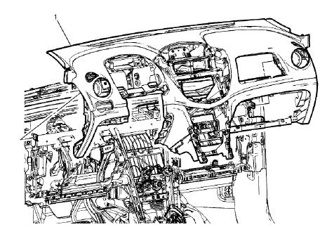
Fig. 47: Instrument Panel And Electrical Harness Assembly
- With the aid of an assistant, load the instrument panel (1) to the instrument panel tie bar to the locator pins.
- Reposition the instrument panel wiring harness into the vehicle position as was noted in the removal and connect the fasteners securing the instrument panel wiring harness to the instrument carrier (1).
.gif)
Fig. 48: Instrument Panel Bolts
CAUTION: Refer to Fastener Caution .
- Install the instrument panel bolts (1).
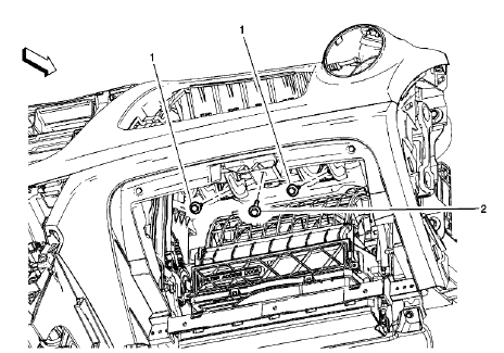
Fig. 49: Instrument Panel Inflatable Restraint Module Bracket And Bolts
- Install the instrument panel inflatable restraint module bracket bolts (1) and tighten to 9 N.m (80 lb in).
- Install the instrument panel compartment door latch striker bolt (2) and tighten to 9 N.m (80 lb in).
.gif)
Fig. 50: Sun Load Temperature Sensor Bezel
- Install the sun load temperature sensor bezel (1). Refer to Sun Load Temperature Sensor Bezel Replacement (Trax) .
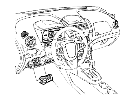
Fig. 51: Headlamp Switch
- Install the headlamp switch (1). Refer to Headlamp Switch Replacement (Trax)
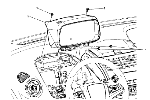
Fig. 52: Instrument Cluster
- Install the instrument cluster (2). Refer to Instrument Cluster Replacement (Trax) .
.gif)
Fig. 53: Steering Column Upper Support Bracket
- Install the steering column. Refer to Steering Column Replacement (Mexico, N40) , Steering Column Replacement (Canada, NJ1) , Steering Column Replacement (United States, NJ1) .
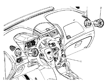
Fig. 54: Instrument Panel Outer Air Outlet
- Install the instrument panel outer air outlets (1) left side and (2) right side. Refer to Instrument Panel Outer Air Outlet Replacement (Trax) .
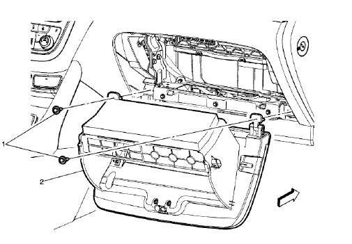
Fig. 55: Instrument Panel Compartment
- Install the instrument panel compartment (2). Refer to Instrument Panel Compartment Replacement.
.gif)
Fig. 56: Instrument Panel Upper Compartment
- Install the instrument panel upper compartment (3). Refer to Instrument Panel Upper Compartment Replacement (Trax).
.gif)
Fig. 57: Instrument Panel Lower Center Trim Plate Applique
- Install the instrument panel lower center trim plate applique (2). Refer to Instrument Panel Lower Center Trim Plate Applique Replacement (Trax).
.gif)
Fig. 58: Radio
- Install the radio (2). Refer to Radio Replacement (Trax) .
.gif)
Fig. 59: Instrument Panel Upper Center Compartment
- Install the instrument panel upper center compartment (3). Refer to Instrument Panel Upper Center Compartment Replacement.
.gif)
Fig. 60: Instrument Panel Outer Trim Covers
- Install the instrument panel outer trim covers (1) left side and (2) right side. Refer to Instrument Panel Outer Trim Cover Replacement (Trax).
.gif)
Fig. 61: Front Floor Console Stowage Tray
- Install the front floor console stowage tray (2). Refer to Front Floor Console Stowage Tray Replacement (Trax).
.gif)
Fig. 62: Front Floor Console
- Install the front floor console (2). Refer to Front Floor Console Replacement (Trax).
.gif)
Fig. 63: Windshield Garnish Molding
- Install both of the windshield garnish moldings (1). Refer to Windshield Garnish Molding Replacement (Trax) .
- Enable the SIR system. Refer to SIR Disabling and Enabling .
