Chevrolet Trax: Engine front cover and oil pump cleaning and inspection
Engine Front Cover Cleaning Procedure
- Clean the engine front cover sealing surface.
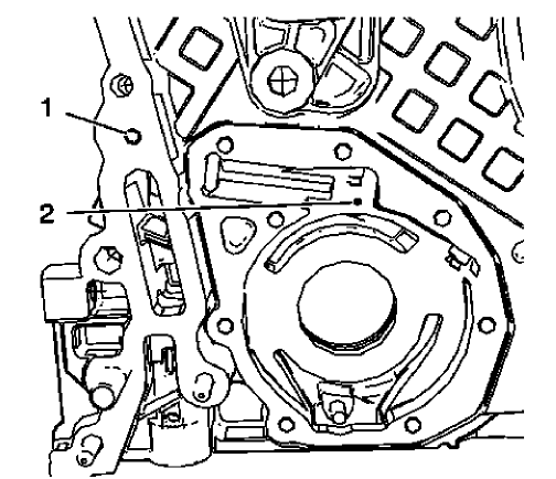
Fig. 366: Oil Gallery Bores
WARNING: Wear safety glasses when using compressed air in order to prevent eye injury.
CAUTION: To ensure proper engine lubrication, clean clogged or contaminated oil galleries in an approved solvent and with compressed air. Failure to clean oil galleries may cause engine damage.
- Clean the shown oil gallery with solvent and compressed air. Blow compressed air from bore (2) to bore (1).
Engine Front Cover Visual Inspection
Inspect the engine front cover for cracks, scratches and damage.
Oil Pump Visual Inspection and Measurement
- Inspect the oil pump cover and the engine front cover for flatness.
- Inspect the oil pump vanes, the oil pump vane rotor, the oil pump vane rings and the oil pump slide for localized flatting.
- Inspect the oil pump slide pivot pin for firm seat.
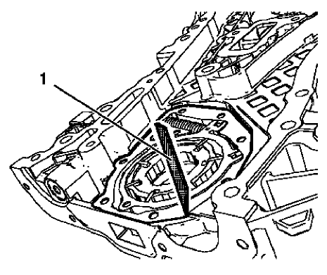
Fig. 367: Straight Edge Tool
NOTE: Oil pump components are installed.
- Measure the oil pump axial clearances. Use a straight edge (1) and a feeler gauge.
- The maximal axial clearance between engine front cover and oil pump vane rotor should be 0.1 mm (0.004 in).
- The maximal axial clearance between engine front cover and oil pump vane should be 0.09 mm (0.0035 in).
- The maximal axial clearance between engine front cover and oil pump vane ring should be 0.4 mm (0.016 in).
- The maximal axial clearance between engine front cover and oil pump slide should be 0.08 mm (0.0031 in).
- The maximal axial clearance between engine front cover and oil pump slide seal should be 0.09 mm (0.0035 in).
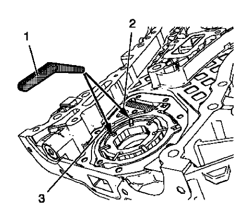
Fig. 368: Feeler Gauge, Oil Pump Slide And Oil Pump Vane
- Measure the oil pump radial clearance. Use a feeler gauge (1). Measure the clearance between oil pump vane rotor and oil pump vane (3).
The maximal clearance should be 0.05 mm (0.002 in).
- Measure the clearance between oil pump vane and oil pump slide (2).
The maximal clearance should be 0.2 mm (0.008 in).
ENGINE FRONT COVER AND OIL PUMP DISASSEMBLE
Engine Front Cover Disassemble
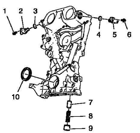
Fig. 369: Locating Engine Front Cover Components
- Remove the intake camshaft position sensor bolt (1).
- Remove the intake camshaft position sensor (2) and the seal ring (3).
- Remove the exhaust camshaft position sensor bolt (6).
- Remove the exhaust camshaft position sensor (5) and the seal ring (4).
- Remove the oil pressure relief valve (7, 8 and 9)
- Remove the crankshaft front oil seal (10).
Oil Pump Removal
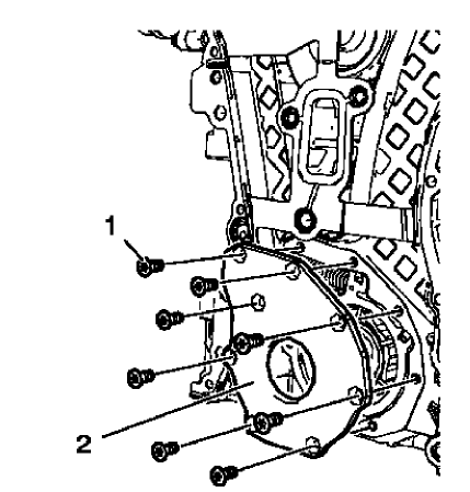
Fig. 370: Engine Oil Pump Cover And Bolts
- Remove the 8 oil pump cover bolts (1).
- Remove the oil pump cover (2).
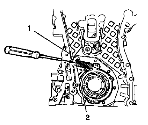
Fig. 371: Oil Pump Slide Spring Windings And Engine Front Cover Edge
WARNING: Before removing the spring, cover the spring with a towel to prevent the spring from flying and possibly causing damage or personal injury.
NOTE: Position a screw driver between the oil pump slide spring windings (2).
- Protect the engine front cover edge (1) with a suitable piece of plastic.
- Compress the oil pump slide spring with a screw driver and remove the oil pump slide spring along with the oil pump slide spring pin.
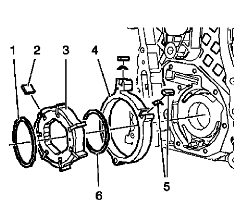
Fig. 372: Locating Engine Oil Pump Components
NOTE: Mind the installation position of the oil pump components.
- Remove the oil pump components in the following order:
- Outer oil pump vane ring (1).
- Oil pump vane rotor (3) and the 7 oil pump vanes (2).
- Inner oil pump vane ring (6).
- Oil pump slide (4) and the 2 oil pump slide seals with the 2 oil pump slide seal springs (5).
TURBOCHARGER DISASSEMBLE
Special Tool
EN-49940 Remover Quick Connector
For equivalent regional tools, refer to Special Tools.
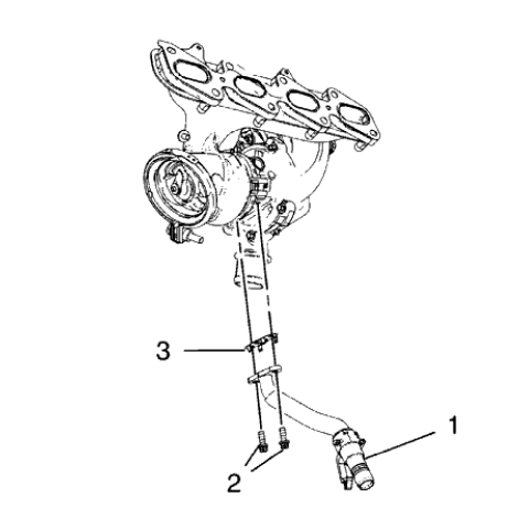
Fig. 373: Turbocharger Oil Return Pipe
- Remove the 2 turbocharger oil return pipe bolts (2).
- Remove the turbocharger oil return pipe (1) and the sealing (3) from the turbocharger.
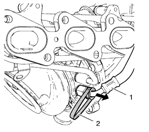
Fig. 374: Turbocharger Coolant Feed Pipe
NOTE: The quick fitting connectors should be always replaced when the turbocharger coolant pipes are removed
- Install the EN-49940 remover (2) to the turbocharger coolant feed pipe (1) and the quick fitting connector as shown.
- Compress the EN-49940 remover and remove the turbocharger coolant feed pipe direction of the arrow.
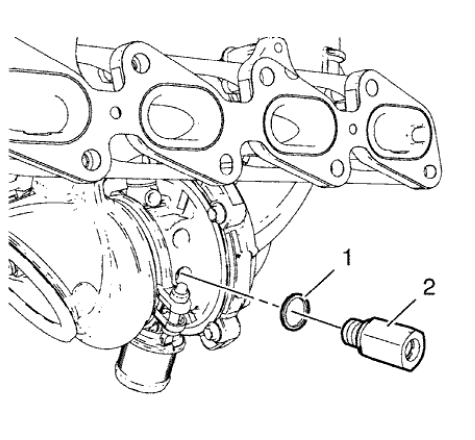
Fig. 375: Quick Fitting Connector And Seal Ring
- Remove the quick fitting connector (2) and the seal ring (1).
- Use the same procedure for the turbocharger coolant return pipe and the turbocharger coolant return pipe quick fitting connector.
TURBOCHARGER CLEANING AND INSPECTION
Cleaning Procedure
- Clean all sealing surfaces.
- Clean all threads if necessary.
Inspection Procedure
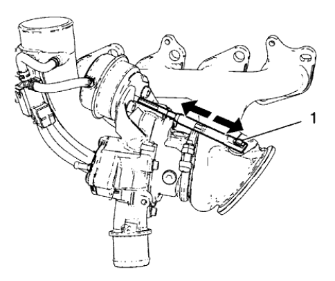
Fig. 376: Wastegate Regulator Mechanism
- Inspect the wastegate regulator mechanism (1) for functionality.
- Inspect the turbine blades for damage or foreign material.
- Inspect the turbocharger wastegate regulator vacuum hoses for damage.
- Inspect the exhaust manifold and the turbocharger for cracks or other damage.
- Inspect the exhaust manifold mating surface for flatness.
TURBOCHARGER ASSEMBLE
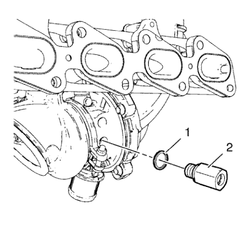
Fig. 377: Quick Fitting Connector And Seal Ring
CAUTION: Refer to Fastener Caution .
- Install the NEW quick fitting connector (2) and a NEW seal ring (1) to the turbocharger and tighten to 20 N.m (15 lb ft).
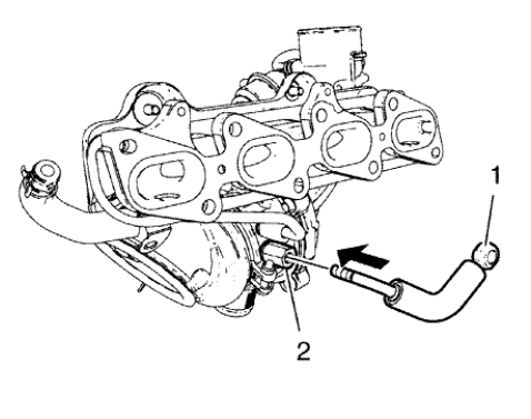
Fig. 378: Turbocharger Coolant Feed Pipe And Quick Fitting Connector
- Inspect the turbocharger coolant pipes for ridges and damage.
- Install the turbocharger coolant feed pipe (1) to the quick fitting connector (2) by pushing in direction of the arrow until an audible click is heard.
- Use the same procedure for the turbocharger coolant return pipe and the turbocharger coolant return pipe quick fitting connector.
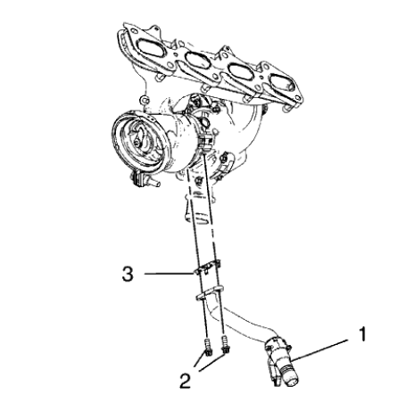
Fig. 379: Turbocharger Oil Return Pipe
- Install the turbocharger oil return pipe (1) and a NEW sealing (3) to the turbocharger.
- Install the 2 turbocharger oil return pipe bolts (2) and tighten to 8 N.m (71 lb in).
ENGINE OIL COOLER DISASSEMBLE
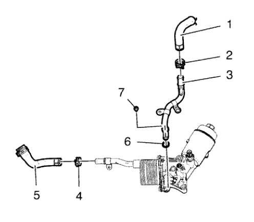
Fig. 380: Locating Engine Oil Cooler Components
- Remove the oil cooler coolant inlet hose clamp (2).
- Remove the oil cooler coolant inlet hose (1).
- Remove the oil cooler coolant inlet pipe bolt (7)
- Remove the oil cooler coolant inlet pipe (3) and the seal ring (6).
- Remove the oil cooler coolant outlet hose clamp (4).
- Remove the oil cooler coolant outlet hose (5).
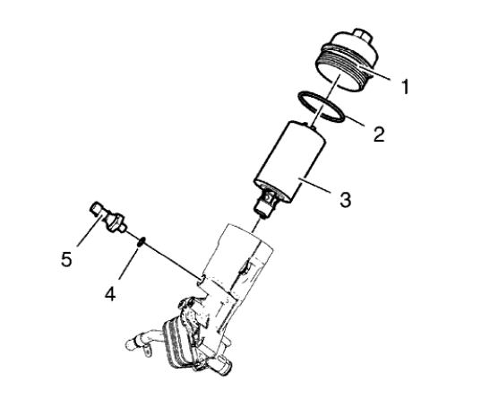
Fig. 381: Engine Oil Pressure Indicator Switch, Oil Filter Cap And Oil Filter
Element
- Remove the engine oil pressure indicator switch (5) and the seal ring (4).
- Remove the engine oil filter cap (1) along with the seal ring (2) and the oil filter element (3).
ENGINE OIL COOLER ASSEMBLE
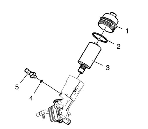
Fig. 382: Engine Oil Pressure Indicator Switch, Oil Filter Cap And Oil Filter
Element
CAUTION: Refer to Fastener Caution .
- Install the engine oil filter cap (1) along with a NEW seal ring (2) and a NEW oil filter element (3) and tighten to 25 N.m (18 lb ft).
- Install the engine oil pressure indicator switch (5) and NEW seal ring (4) and tighten to 20 N.m (15 lb ft).
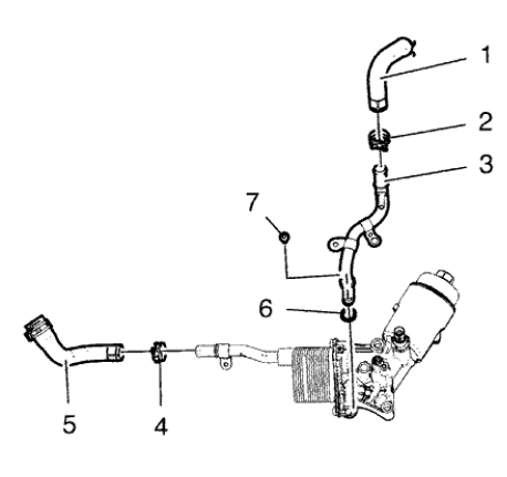
Fig. 383: Locating Engine Oil Cooler Components
- Install the oil cooler coolant outlet hose (5)
- Install the oil cooler coolant outlet hose clamp (4).
- Install the oil cooler coolant inlet pipe (3) and a NEW seal ring (6).
- Install the oil cooler coolant inlet pipe bolt (7) and tighten to 10 N.m (89 lb in).
- Install the oil cooler coolant inlet hose (1).
- Install oil cooler coolant inlet hose clamp (2).
OIL PAN CLEANING AND INSPECTION
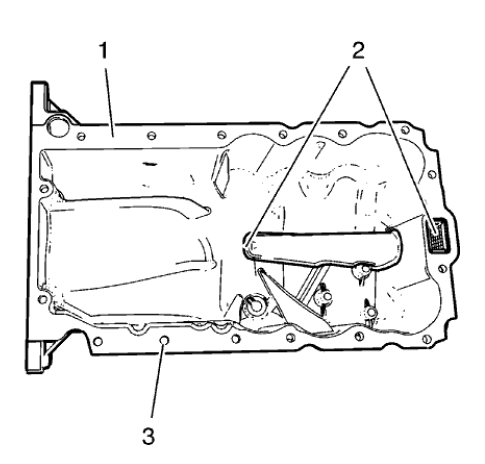
Fig. 384: Oil Suction Gallery, Sealing Surface And Screw Bores
WARNING: Wear safety glasses when using compressed air in order to prevent eye injury.
CAUTION: To ensure proper engine lubrication, clean clogged or contaminated oil galleries in an approved solvent and with compressed air. Failure to clean oil galleries may cause engine damage.
- Clean the oil suction gallery (2) with compressed air. Be sure to remove all dirt and old gasket material from the suction gallery (2).
- Remove all remaining old gasket material from sealing surface (1) and screw bores (3).
- Clean the sealing surfaces from dirt and grease.
- Inspect the sealing surface for cracks and damage.

