Chevrolet Trax: Cylinder head installation
Special Tools
EN-470-B Angular Torque Wrench.
For equivalent regional tools, refer to Special Tools.
WARNING: Wear safety glasses when using compressed air in order to prevent eye injury.
- Clean the sealing surfaces and remove dirt and old gasket material from thread bores, water galleries and oil galleries.
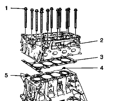
Fig. 399: Cylinder Head, Gasket, Bolts And Guide Sleeves
NOTE: Mind the guide sleeves (4) and (5).
- Install a NEW cylinder head gasket (3). The marking "Top" should point to the cylinder head.
- Install the cylinder head (2).
- Install 12 NEW cylinder head bolts (1) and hand tighten.
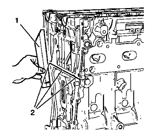
Fig. 400: Straight Edge Tool
- Lay a straight edge (1) against the engine block and cylinder head. Adjust the transition in area (2) until there is no clearance between cylinder head and straight edge, using a rubber mallet.
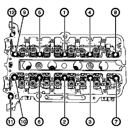
Fig. 401: Cylinder Head Bolts Tightening Sequence
CAUTION: Refer to Fastener Caution
CAUTION: Refer to Torque-to-Yield Fastener Caution .
- Tighten the cylinder head bolts in the sequence shown and to the following specifications:
- Tighten the cylinder head bolts to 35 N.m (26 lb ft).
- Tighten the cylinder head bolts an additional 180 degrees. Use EN-470-B wrench.
HYDRAULIC VALVE LASH ADJUSTER INSTALLATION
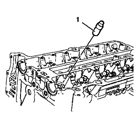
Fig. 402: Hydraulic Valve Lash Adjusters
NOTE: Mind the installation position of the hydraulic valve lash adjusters.
- Lubricate the hydraulic valve lash adjusters with engine oil.
- Install the 16 hydraulic valve lash adjusters (1).
HYDRAULIC VALVE LASH ADJUSTER ARM INSTALLATION
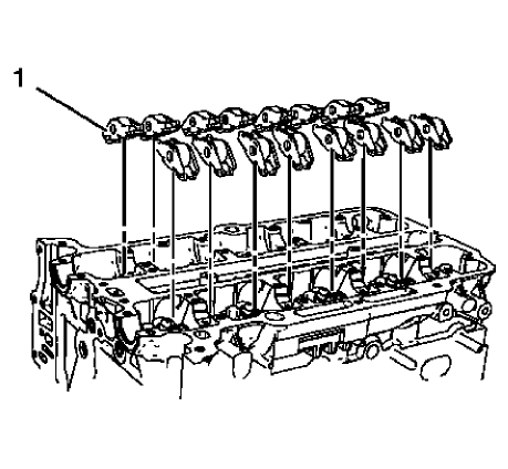
Fig. 403: Hydraulic Valve Lash Adjuster Arms
NOTE: Hydraulic valve lash adjuster arms should be installed in their original position.
- Lubricate the hydraulic valve lash adjuster arms with engine oil.
- Install the 16 hydraulic valve lash adjuster arms (1).
INTAKE CAMSHAFT INSTALLATION
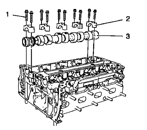
Fig. 404: Intake Camshaft, Camshaft Bearing Caps And Bolts
NOTE: Mind the markings on the camshaft bearing caps. Camshaft bearing caps should be installed in their original position.
- Lubricate camshaft and camshaft bearing caps with engine oil.
- Install the intake camshaft (3).
- Install the 5 camshaft bearing caps (2).
- Install the 10 camshaft bearing cap bolts (1) and handtighten
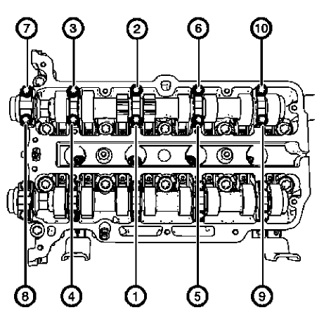
Fig. 405: Intake Camshaft Bearing Cap Bolts Tightening Sequence
CAUTION: Refer to Fastener Caution .
NOTE: Tighten the camshaft bearing cap bolts one turn at a time in order to avoid shape distortion of the camshaft.
- Tighten the camshaft bearing cap bolts one turn at a time and in a spiral sequence as shown to 8 N.m (71 lb in).
EXHAUST CAMSHAFT INSTALLATION
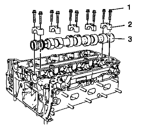
Fig. 406: Exhaust Camshaft, Camshaft Bearing Caps And Bolts
NOTE: Mind the markings on the camshaft bearing caps. Camshaft bearing caps should be installed in their original position.
- Lubricate camshaft and camshaft bearing caps with engine oil.
- Install the exhaust camshaft (3).
- Install the 5 camshaft bearing caps (2).
- Install the 10 camshaft bearing cap bolts (1) and handtighten.
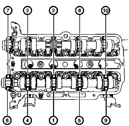
Fig. 407: Exhaust Camshaft Bearing Cap Bolts Tightening Sequence
CAUTION: Refer to Fastener Caution .
NOTE: Tighten the camshaft bearing cap bolts one turn at a time in order to avoid shape distortion of the camshaft.
- Tighten the camshaft bearing cap bolts one turn at a time and in a spiral sequence as shown to 8 N.m (71 lb in).
CAMSHAFT SPROCKET INSTALLATION
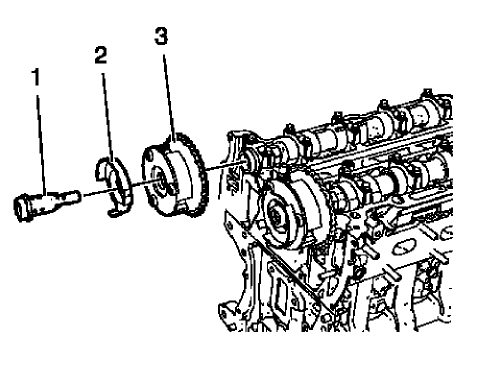
Fig. 408: Intake Camshaft Sprocket, Bolt And Intake Camshaft Position Exciter
Wheel
- Install the intake camshaft sprocket (3).
- Install the intake camshaft position sensor exciter wheel (2) and the intake camshaft sprocket bolt (1), but do not tighten yet.
- Install the exhaust camshaft sprocket.
NOTE: Tightening of camshaft sprocket bolts will be done after the engine front cover installation.
- Install the exhaust camshaft position sensor exciter wheel and the exhaust camshaft sprocket bolt, but do not tighten yet.
TIMING CHAIN TENSIONER INSTALLATION
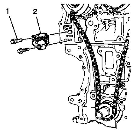
Fig. 409: Timing Chain Tensioner And Bolts
- Install the timing chain tensioner (2).
CAUTION: Refer to Fastener Caution .
- Install the 2 timing chain tensioner bolts (1) and tighten to 8 N.m (71 lb in).
ENGINE FRONT COVER GASKET INSTALLATION
- Clean the sealing surfaces and remove all remains of old sealing compound material.
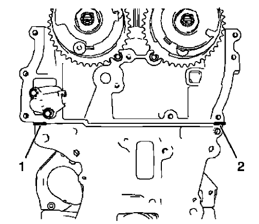
Fig. 410: Sealing Compound Application Areas
NOTE: The thickness of the sealing bead should be 2 mm (0.0787 in).
- Apply sealing compound to the shown areas (1) and (2). Refer to Adhesives, Fluids, Lubricants, and Sealers.
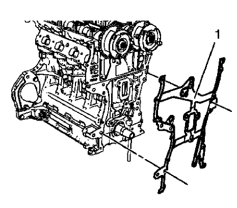
Fig. 411: Engine Front Cover Gasket
NOTE: Mind the guide sleeves.
- Install the NEW engine front cover gasket (1).
- Install the timing chain. Refer to Camshaft Timing Chain Installation.
NOTE: The complete installation procedure should not take longer than 10 minutes.
- Install the engine front cover. Refer to Engine Front Cover and Oil Pump Installation.

