Chevrolet Trax: Oil pan installation
Special Tools
EN-49980 Guidance Pins
For equivalent regional tools, refer to Special Tools.
- Clean the sealing surfaces from old sealing material, dirt, oil and grease.
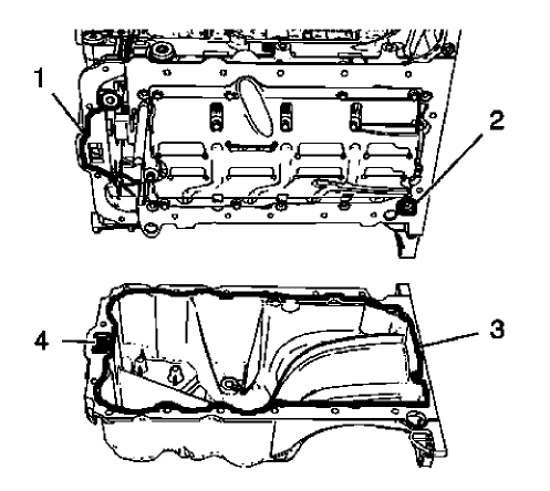
Fig. 421: Engine Front Cover, Oil Suction Gallery And Screw Bore
NOTE: The sealing bead should be applied close to the inner edge of the oil pan.
Take care that the oil suction gallery (4) will not get contaminated with sealing compound or dirt. The thickness of the sealing bead (3) should be 2 mm (0.0787 in).
- Apply sealing compound to the oil pan. Refer to Adhesives, Fluids, Lubricants, and Sealers.
- Apply sealing compound to the groove of the engine front cover (1). Refer to Adhesives, Fluids, Lubricants, and Sealers.
- Apply sealing compound around the screw bore (2) of the crankshaft bearing cap tie plate.
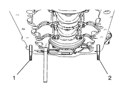
Fig. 422: Engine Oil Pan Pins
NOTE: The complete installation procedure of the oil pan should not take longer than 10 minutes.
- Install the 2 EN-49980 pins (1) and (2) to the shown oil pan screw bores.
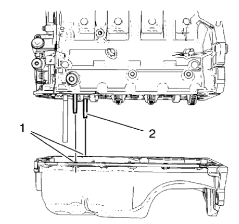
Fig. 423: Engine Oil Pan Pins And Screw Bores
CAUTION: Use care when installing the oil pan to prevent disruption of the sealing bead. The sealing bead should remain consistent until the oil pan is mated with the engine. An inconsistent sealing bead can cause an insufficient seal and result in engine damage.
- Carefully install the oil pan. Guide the oil pan with EN-49980 pins (2) and the equivalent screw bores (1).
- Hold the oil pan with 4 oil pan bolts.
- Remove EN-49980 pins.
- Install the remaining 12 oil pan bolts and hand tighten.
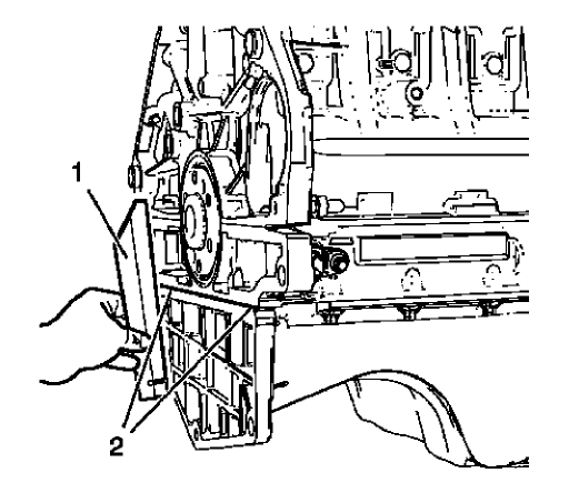
Fig. 424: Straight Edge Tool
- Lay a straight edge (1) against the oil pan and engine block. Using a rubber mallet, adjust the transition in area (2) until there is no clearance between oil pan and the straight edge.
CAUTION: Refer to Fastener Caution .
- Tighten the 16 oil pan bolts to 10 N.m (89 lb in).
CAMSHAFT POSITION ACTUATOR SOLENOID VALVE INSTALLATION
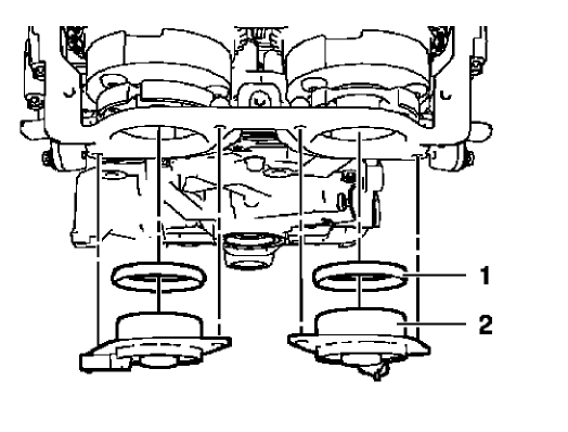
Fig. 425: Camshaft Position Actuator Solenoid Valves And Seal Rings
CAUTION: The camshaft position actuator solenoid valves must be kept parallel to the engine front cover during removal and installation. The camshaft position actuator solenoid valves can be damaged if they become wedged or stuck during this process.
- Install the 2 camshaft position actuator solenoid valves (2) and the 2 seal rings (1) by carefully and evenly pressing.
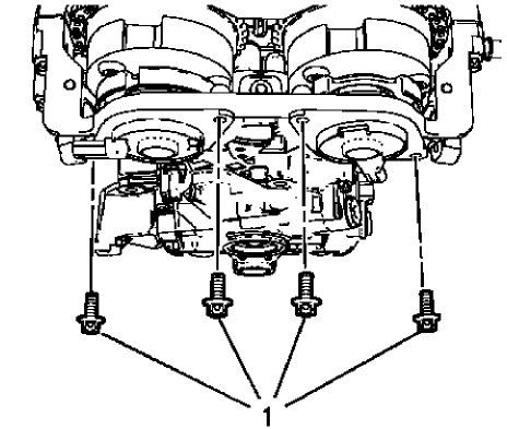
Fig. 426: Camshaft Position Actuator Solenoid Valve Bolts
CAUTION: Refer to Fastener Caution
- Install the 4 camshaft position actuator solenoid valve bolts (1) and tighten to 8 N.m (71 lb in).
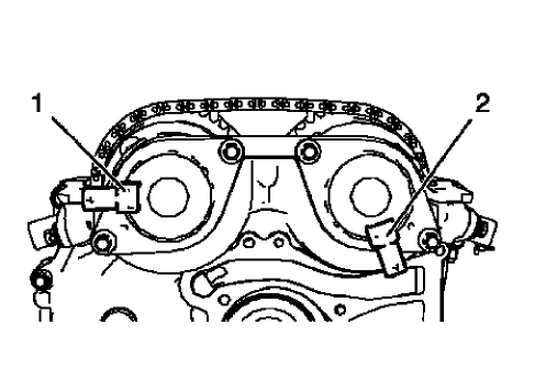
Fig. 427: Camshaft Position Actuator Solenoid Valves Proper Position
- The 2 camshaft position actuator solenoid valves should be installed in the position as shown (1) and (2).
CAMSHAFT COVER INSTALLATION
- Clean the sealing surfaces.
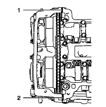
Fig. 428: Sealing Compound Application Areas
NOTE: The thickness of the sealing bead should be 2 mm (0.0787 in).
- Apply sealing compound to areas (1) and (2). Refer to Adhesives, Fluids, Lubricants, and Sealers.
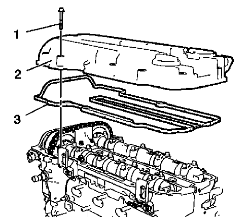
Fig. 429: Camshaft Cover And Gasket
NOTE: The installation procedure should not take longer than 10 minutes.
- Install the camshaft cover (2) and a NEW gasket (3).
- Install the 15 camshaft cover bolts (1).
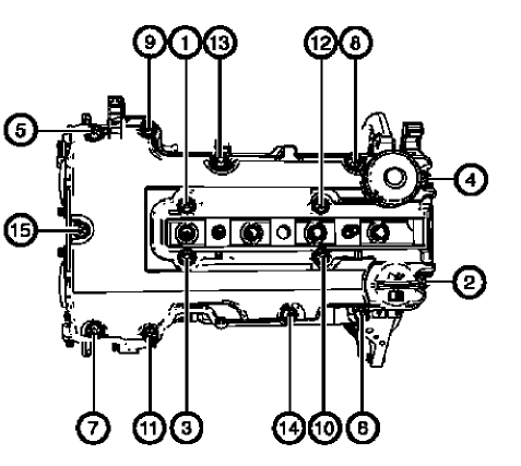
Fig. 430: Camshaft Cover Bolts Tightening Sequence
- Tighten the 15 camshaft cover bolts in a sequence as shown to 8 N.m (71 lb in).
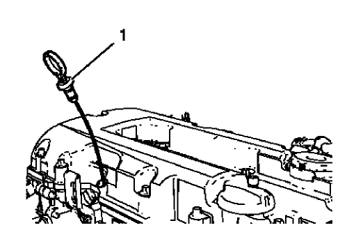
Fig. 431: Engine Oil Level Indicator
- Install the oil level indicator (1).
IGNITION COIL INSTALLATION
Special Tools
EN-6009 Remover and Installer Ignition Module
For equivalent regional tools, refer to Special Tools.
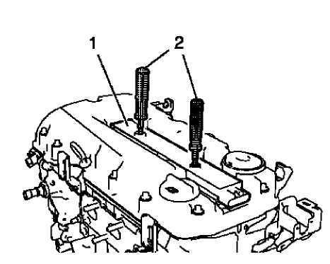
Fig. 432: Ignition Coil And Remover/Installer
- Install the ignition coil (1) and remove EN-6009 remover and installer (2).
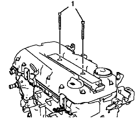
Fig. 433: Ignition Coil Bolts
CAUTION: Refer to Fastener Caution .
- Install the 2 ignition coil bolts (1) and tighten to 8 N.m (71 lb in).
ENGINE FLYWHEEL INSTALLATION
Special Tools
- EN-470-B Angular Torque Wrench
- EN-652 Flywheel Holder
For equivalent regional tools, refer to Special Tools.
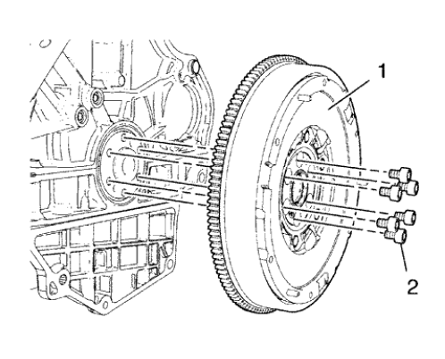
Fig. 434: Engine Flywheel And Bolts
- Install the engine flywheel (1).
- Install the 6 NEW engine flywheel bolts (2).
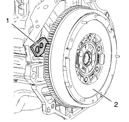
Fig. 435: Engine Flywheel And Holder
- Install EN-652 holder (1) to hold the engine flywheel (2).
CAUTION: Refer to Fastener Caution .
CAUTION: Refer to Torque-to-Yield Fastener Caution .
- Tighten the 6 engine flywheel bolts in a cross sequence to 60 N.m (44 lb ft).
- Tighten the 6 engine flywheel bolts in a cross sequence to an additional 45 degrees. Use EN-470-B wrench.
- Tighten the 6 engine flywheel bolts in a cross sequence to an additional 15 degrees. Use EN-470-B wrench.
- Remove EN-652 holder.
GENERATOR INSTALLATION
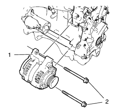
Fig. 436: Generator And Bolts
- Install the generator (1).
CAUTION: Refer to Fastener Caution .
- Install the 2 generator bolts (2) and tighten to 35 N.m (26 lb ft)

