Chevrolet Trax: Crankshaft and bearing installation
Special Tools
- EN-235-6 Installer from EN-235-D Kit.
- EN-470-B Angular Torque Wrench
- EN-658-1 Installer from EN-658 Kit
For equivalent regional tools, refer to Special Tools.
- Lubricate crankshaft, crankshaft bearings and crankshaft bearing cap tie plate with engine oil.
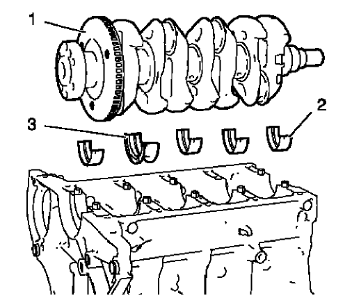
Fig. 385: Crankshaft, Upper Crankshaft Bearings And Upper Crankshaft Thrust
Bearing
- Install the 4 upper crankshaft bearings (2) and the crankshaft thrust bearing (3).
- Install the crankshaft (1).
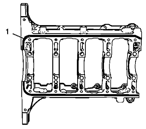
Fig. 386: Sealing Compound Application Area
NOTE: The thickness of the sealing bead should be 2 mm (0.0787 in).
- Apply sealing compound (1) to the outer rim of the groove on the crankshaft bearing cap tie plate. Refer to Adhesives, Fluids, Lubricants, and Sealers.
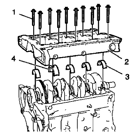
Fig. 387: Crankshaft Bearing Cap Tie Plate
NOTE: The complete installation procedure should not take longer than 10 minutes.
- Install the 4 lower crankshaft bearings (3) and the lower crankshaft thrust bearing (4).
- Install the crankshaft bearing cap tie plate (2).
NOTE: Do not reuse the old bolts.
- Install the 10 NEW inner crankshaft bearing cap tie plate bolts (1).
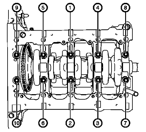
Fig. 388: Inner Crankshaft Bearing Cap Tie Plate Bolts Tightening Sequence
CAUTION: Refer to Fastener Caution .
CAUTION: Refer to Torque-to-Yield Fastener Caution .
- Tighten the 10 inner crankshaft bearing cap tie plate bolts in the sequence shown and to the following specifications:
- Tighten the inner crankshaft bearing cap tie plate bolts to 25 N.m (18 lb ft).
- Tighten the inner crankshaft bearing cap tie plate bolts an additional 60 degrees. Use EN-470-B wrench.
- Tighten the inner crankshaft bearing cap tie plate bolts an additional 15 degrees. Use EN-470-B wrench.
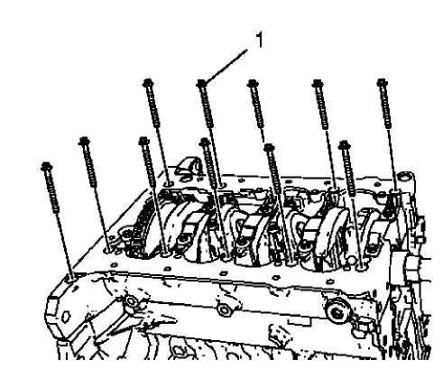
Fig. 389: Outer Crankshaft Bearing Cap Tie Plate Bolts
NOTE: Do not reuse the old bolts.
- Install the 12 NEW outer crankshaft bearing cap tie plate bolts (1) and tighten to the following specification:
- Tighten the outer crankshaft bearing cap tie plate bolts to 10 N.m (89 lb in).
- Tighten the outer crankshaft bearing cap tie plate bolts an additional 60 degrees. Use EN-470-B wrench.
- Tighten the outer crankshaft bearing cap tie plate bolts an additional 15 degrees. Use EN-470-B wrench.
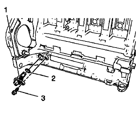
Fig. 390: Crankshaft Position Sensor, Bolt And Seal Ring
- Install the crankshaft position sensor (1) and a NEW crankshaft position sensor seal ring (2).
- Install the crankshaft position sensor bolt (3) and tighten to 8 N.m (71 lb in).
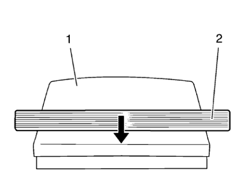
Fig. 391: Crankshaft Rear Oil Seal
- Slide the crankshaft rear oil seal (2) across the EN-235-6 installer (1) contained in EN-235-D kit.
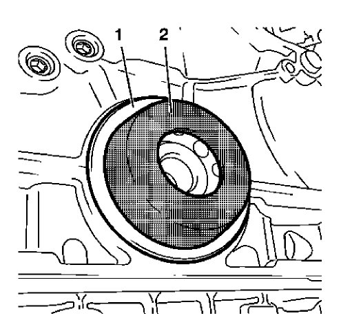
Fig. 392: Crankshaft Rear Oil Seal And Installer
- Install the crankshaft rear oil seal (1) with EN-235-6 installer (2) to the crankshaft.
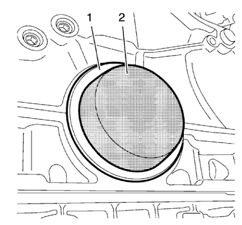
Fig. 393: Oil Seal Installer
NOTE: Ensure that the crankshaft rear oil seal fits proper.
- Use EN-658-1 installer (2) to strike the crankshaft rear oil seal (1)
PISTON, CONNECTING ROD, AND BEARING INSTALLATION
Special Tools
EN-470-B Angular Torque Wrench
For equivalent regional tools, refer to Special Tools.
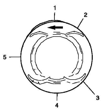
Fig. 394: Piston Ring Joint Adjustment Points
- Adjust the piston ring joints as follows:
- Upper compression ring (1).
- Lower compression ring (4).
- Oil rings (2) or (3).
- Oil ring spacer (5)
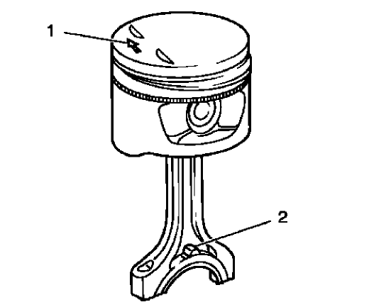
Fig. 395: Rods And Arrow On Piston Head
- The arrow (1) on the piston head must point to the timing side.
- The markings on the connecting rods (2) must point to the transmission side.
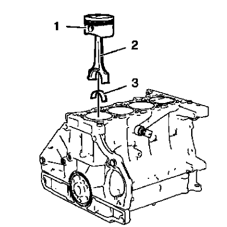
Fig. 396: Pistons, Connecting Rods And Bearings
- Install a piston ring compressor to compress the piston rings.
- Install the pistons (1) in along with connecting rods (2) and upper connecting rod bearings (3) to the engine block and to the crankshaft.
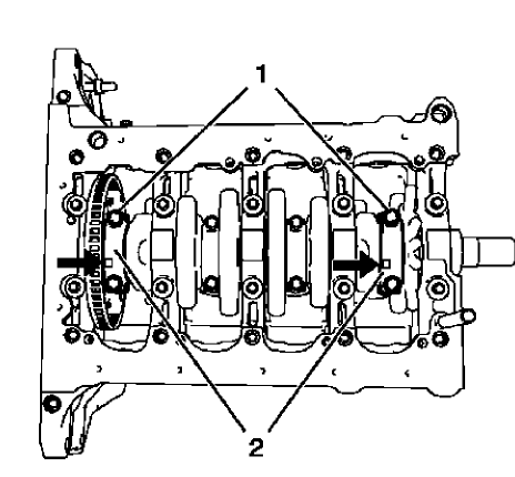
Fig. 397: Rod Bearing Caps And Bolts
NOTE: The flarings (arrows) on the connecting rod bearing caps must point to the transmission side. The connecting rod bearing caps must be installed in their original position.
- Install the 2 connecting rod bearings and the 2 connecting rod bearing caps (2) of cylinder 1 and 4.
CAUTION: Refer to Fastener Caution
CAUTION: Refer to Torque-to-Yield Fastener Caution .
NOTE: Do not reuse the old bolts.
- Install the 4 NEW connecting rod bearing cap bolts (1) and tighten in the following sequence:
- Tighten the connecting rod bearing cap bolts to 25 N.m (18 lb ft).
- Tighten the connecting rod bearing cap bolts an additional 45 degrees. Use EN-470 B wrench
- Rotate the crankshaft 180 degrees.
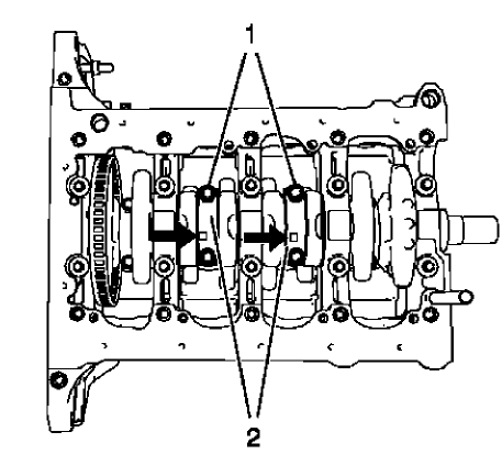
Fig. 398: Rod Bearing Caps And Bolts
NOTE: The flarings (arrows) on the connecting rod bearing caps must point to the transmission side. The connecting rod bearing caps must be installed in their original position.
- Install the 2 connecting rod bearings and the 2 connecting rod bearing caps (2) of cylinder 3 and 2.
NOTE: Do not reuse the old bolts.
- Install the 4 NEW connecting rod bearing cap bolts (1) and tighten in the following sequence:
- Tighten the connecting rod bearing cap bolts to 25 N.m (18 lb ft).
- Tighten the connecting rod bearing cap bolts an additional 45 degrees. Use EN-470-B wrench.

