Chevrolet Trax: Engine control module description
The Engine Control Module (ECM) interacts with many emission related components and systems, and monitors emission related components and systems for deterioration. OBD II diagnostics monitor the system performance and a diagnostic trouble code (DTC) sets if the system performance degrades. The ECM is part of a network and communicates with various other vehicle control modules.
Malfunction indicator lamp (MIL) operation and DTC storage are dictated by the DTC type. A DTC is ranked as a Type A or Type B if the DTC is emissions related. Type C is a non-emissions related DTC.
The ECM is the control center of the engine controls system. Review the components and wiring diagrams in order to determine which systems are controlled by the ECM.
The ECM constantly monitors the information from various sensors and other inputs, and controls the systems that affect engine performance and emissions. The ECM also performs diagnostic tests on various parts of the system and can turn on the MIL when it recognizes an operational problem that affects emissions. When the ECM detects a malfunction, the ECM stores a DTC. The condition area is identified by the particular DTC that is set. This aids the technician in making repairs.
ECM Function
The ECM can supply 5 V or 12 V to various sensors or switches. This is done through pull-up resistors to regulated power supplies within the ECM. In some cases, even an ordinary shop voltmeter will not give an accurate reading due to low input resistance. Therefore, a digital multimeter (DMM) with at least 10 megaohms input impedance is required in order to ensure accurate voltage readings.
The ECM controls the output circuits by controlling the ground or the power feed circuit through transistors or a device called an output driver module.
EEPROM
The electronically erasable programmable read only memory (EEPROM) is an integral part of the ECM. The EEPROM contains program and calibration information that the ECM needs in order to control engine operation.
Special equipment, as well as the correct program and calibration for the vehicle, are required in order to reprogram the ECM.
Data Link Connector (DLC)
The data link connector (DLC) provides serial data communication for ECM diagnosis. This connector allows the technician to use a scan tool in order to monitor various serial data parameters, and display DTC information. The DLC is located inside the driver's compartment, underneath the instrument panel.
Malfunction Indicator Lamp (MIL)
The malfunction indicator lamp (MIL) is inside the instrument panel cluster (IPC). The MIL is controlled by the ECM and illuminates when the ECM detects a condition that affects vehicle emissions.
ECM Service Precautions
The ECM, by design, can withstand normal current draws that are associated with vehicle operations. However, care must be used in order to avoid overloading any of these circuits. When testing for opens or shorts, do not ground or apply voltage to any of the ECM circuits unless the diagnostic procedure instructs you to do so.
These circuits should only be tested with a DMM unless the diagnostic procedure instructs otherwise.
Emissions Diagnosis For State I/M Programs
This OBD II equipped vehicle is designed to diagnose any conditions that could lead to excessive levels of the following emissions:
- Hydrocarbons (HC)
- Carbon monoxide (CO)
- Oxides of nitrogen (NOx)
- Evaporative emission (EVAP) system losses
Should this vehicle's on-board diagnostic system (ECM) detect a condition that could result in excessive emissions, the ECM turns ON the MIL and stores a DTC that is associated with the condition.
Aftermarket (Add-On) Electrical And Vacuum Equipment
CAUTION: Do not attach add-on vacuum operated equipment to this vehicle. The use of add-on vacuum equipment may result in damage to vehicle components or systems.
CAUTION: Connect any add-on electrically operated equipment to the vehicle's electrical system at the 12 V battery (power and ground) in order to prevent damage to the vehicle.
Aftermarket, add-on, electrical and vacuum equipment is defined as any equipment installed on a vehicle after leaving the factory that connects to the vehicle's electrical or vacuum systems. No allowances have been made in the vehicle design for this type of equipment.
Add-on electrical equipment, even when installed to these strict guidelines, may still cause the powertrain system to malfunction. This may also include equipment not connected to the vehicle electrical system, such as portable telephones and radios. Therefore, the first step in diagnosing any powertrain condition is to eliminate all of the aftermarket electrical equipment from the vehicle. After this is done, if the problem still exists, the problem may be diagnosed in the normal manner.
Electrostatic Discharge (ESD) Damage
NOTE: In order to prevent possible electrostatic discharge damage to the ECM, DO NOT touch the connector pins on the ECM.
The electronic components that are used in the control systems are often designed to carry very low voltage.
These electronic components are susceptible to damage caused by electrostatic discharge. Less than 100 V of static electricity can cause damage to some electronic components. By comparison, it takes as much as 4,000 V for a person to even feel a static discharge.
There are several ways for a person to become statically charged. The most common methods of charging are by friction and by induction. An example of charging by friction is a person sliding across a car seat.
Charging by induction occurs when a person with well insulated shoes stands near a highly charged object and momentarily touches ground. Charges of the same polarity are drained off leaving the person highly charged with the opposite polarity. Static charges can cause damage, therefore, it is important to use care when handling and testing electronic components.
Emissions Control Information Label
The underhood Vehicle Emissions Control Information Label contains important emission specifications. This identifies the year, the displacement of the engine in liters, and the class of the vehicle.
This label is located in the engine compartment of every General Motors vehicle. If the label has been removed, it can be ordered from GM service parts operations (GMSPO).
EVAPORATIVE EMISSION CONTROL SYSTEM DESCRIPTION
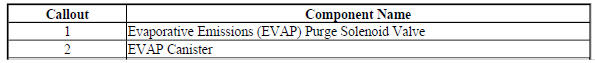
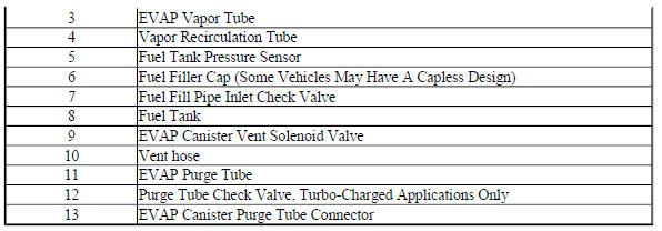
Typical Evaporative Emission (EVAP) System Hose Routing Diagram
.gif)
Fig. 2: View Of Evaporative Emission (EVAP) System Hose Routing Diagram
EVAP System Operation
The evaporative emission (EVAP) control system limits fuel vapors from escaping into the atmosphere. Fuel tank vapors are allowed to move from the fuel tank, due to pressure in the tank, through the EVAP vapor tube, into the EVAP canister. Carbon in the canister absorbs and stores the fuel vapors. Excess pressure is vented through the vent hose and EVAP vent solenoid valve to the atmosphere. The EVAP canister stores the fuel vapors until the engine is able to use them. At an appropriate time, the engine control module (ECM) will command the EVAP purge solenoid valve ON, allowing engine vacuum to be applied to the EVAP canister.
With the normally open EVAP vent solenoid valve OFF, fresh air is drawn through the vent solenoid valve and the vent hose to the EVAP canister. Fresh air is drawn through the canister, pulling fuel vapors from the carbon.
The air/fuel vapor mixture continues through the EVAP purge tube and EVAP purge solenoid valve into the intake manifold to be consumed during normal combustion. The ECM uses several tests to determine if the EVAP system is leaking or restricted.
Purge Solenoid Valve Leak Test
If the EVAP purge solenoid valve does not seal properly fuel vapors could enter the engine at an undesired time, causing driveability concerns. The ECM tests for this by commanding the EVAP purge solenoid valve OFF and the vent solenoid valve ON which seals the system. With the engine running, the ECM then monitors the fuel tank pressure (FTP) sensor for an increase in vacuum. The ECM will log a fault if a vacuum develops in the tank under these test conditions.
Large Leak Test
This diagnostic creates a vacuum condition in the EVAP system. When the enabling criteria has been met, the ECM commands the normally open EVAP vent solenoid valve closed and the EVAP purge solenoid valve open, creating a vacuum in the EVAP system. The ECM then monitors the FTP sensor voltage to verify that the system is able to reach a predetermined level of vacuum within a set amount of time. Failure to achieve the expected level of vacuum indicates the presence of a large leak in the EVAP system or a restriction in the purge path. The ECM will log a fault if it detects a weaker than expected vacuum level under these test conditions.
Canister Vent Restriction Test
If the EVAP vent system is restricted, fuel vapors will not be properly purged from the EVAP canister. The ECM tests this by commanding the EVAP purge solenoid valve ON while commanding the EVAP vent solenoid valve OFF, and then monitoring the FTP sensor for an increase in vacuum. If the vacuum increases more than the expected amount, in a set amount of time, a fault will be logged by the ECM.
Small Leak Test
The engine off natural vacuum diagnostic is the small-leak detection diagnostic for the EVAP system. The engine off natural vacuum diagnostic monitors the EVAP system pressure with the ignition OFF. Because of this, it may be normal for the ECM to remain active for up to 40 min after the ignition is turned OFF. This is important to remember when performing a parasitic draw test on vehicles equipped with engine off natural vacuum.
When the vehicle is driven, the temperature rises in the tank due to heat transfer from the exhaust system. After the vehicle is parked, the temperature in the tank continues to rise for a period of time, then starts to drop. The engine off natural vacuum diagnostic relies on this temperature change, and the corresponding pressure change in a sealed system, to determine if an EVAP system leak is present.
The engine off natural vacuum diagnostic is designed to detect leaks as small as 0.51 mm (0.020 in).
EVAP System Components
The EVAP system consists of the following components
EVAP Purge Solenoid Valve
The EVAP purge solenoid valve controls the flow of vapors from the EVAP system to the intake manifold. The purge solenoid valve opens when commanded ON by the ECM. This normally closed valve is pulse width modulated (PWM) by the ECM to precisely control the flow of fuel vapor to the engine. The valve will also be opened during some portions of the EVAP testing when the engine is running, allowing engine vacuum to enter the EVAP system.
Purge Tube Check Valve
Turbocharged vehicles have a check valve in the purge tube between the EVAP purge solenoid valve and the EVAP canister to prevent pressurization of the EVAP system under boost conditions. Note that the presence of this one-way check valve prevents pressure testing the EVAP system for leaks at the EVAP canister purge tube connector.
EVAP Canister
The canister is filled with carbon pellets used to absorb and store fuel vapors. Fuel vapor is stored in the canister until the ECM determines that the vapor can be consumed in the normal combustion process.
Vapor Recirculation Tube
A vapor path between the fuel fill pipe and the vapor tube to the carbon canister is necessary for Vehicle Onboard Diagnostics to fully diagnose the EVAP system. It also accommodates service diagnostic procedures by allowing the entire EVAP system to be diagnosed from either end of the system.
Fuel Tank Pressure Sensor
The FTP sensor measures the difference between the pressure or vacuum in the fuel tank and outside air pressure. The ECM provides a 5 V reference and a ground to the FTP sensor. Depending on the vehicle, the sensor can be located in the vapor space on top of the fuel tank, in the vapor tube between the canister and the tank, or on the EVAP canister. The FTP sensor provides a signal voltage back to the ECM that can vary between 0.1-4.9 V. A high FTP sensor voltage indicates a low fuel tank pressure or vacuum. A low FTP sensor voltage indicates a high fuel tank pressure.
Fuel Fill Pipe Check Valve
The check valve on the fuel fill pipe is there to prevent spit-back during refueling.
EVAP Vent Solenoid Valve
The EVAP vent solenoid valve controls fresh airflow into the EVAP canister. The valve is normally open. The canister vent solenoid valve is closed only during EVAP system tests performed by the ECM.
Fuel Fill Cap
The fuel fill cap is equipped with a seal and a vacuum relief valve.
Capless Fuel Fill
Some vehicles may have a capless fuel fill design behind a locking fuel door. There is no fuel fill cap to remove. One just fully inserts the fuel nozzle into the fill neck, making sure it latches before refueling. Flapper valves close to seal this interface once the fill nozzle is removed.
