Chevrolet Trax: DTC P0815, P0816, OR P0826
Diagnostic Instructions
- Perform the Diagnostic System Check - Vehicle prior to using this diagnostic procedure.
- Review Strategy Based Diagnosis for an overview of the diagnostic approach.
- Diagnostic Procedure Instructions provides an overview of each diagnostic category.
DTC Descriptors
DTC P0815
Upshift Switch Circuit
DTC P0816
Downshift Switch Circuit
DTC P0826
Up and Down Shift Switch Circuit
Diagnostic Fault Information
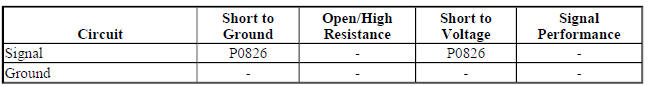
Typical Scan Tool Data
Driver Shift Request
.jpg)
Circuit/System Description
When the shift lever is placed in manual mode (M), the driver shift request , also known as the tap shift function is activated. The driver shift request allows the vehicle operator to shift gears by pushing the plus (+) button for an upshift or minus (-) button for a downshift. The body control module (BCM) supplies a signal circuit to the shift controller. The shift controller has switches connected to a resistor array. When the lever is in the M position, a voltage drop occurs across the resistor network. When the plus or minus button is pushed, a corresponding voltage drop occurs across the resistor network. This voltage drop is monitored by the BCM. The BCM will send the request to the transmission control module (TCM) to perform the upshift or downshift.
The TCM will not allow shifting to the next higher gear if the vehicle speed or engine RPM is too low. The transmission will not allow shifting to the next lower gear if the vehicle speed or engine RPM is too high.
Conditions for Running the DTC
P0815 or P0816
- P0815, P0816, P0826, P1761, P182E, P1876, P1877, or P1915 is not set.
- Engine speed is 400 RPM or greater for 5 s.
- Ignition voltage is 9-32 V.
- Time since the last transmission upshift or downshift is 1 s or greater.
- Runs continuously when above conditions are met.
P0826
- P0826 or P1761 is not set.
- Engine speed is 400-7,500 RPM for 5 s.
- Ignition voltage is 9-32 V.
- Runs continuously when above conditions are met.
Conditions for Setting the DTC
P0815 - Condition 1
TCM detects an upshift request for 1 s with the shift lever in Park or Neutral.
P0815 - Condition 2
TCM detects an upshift request for 10 min with the shift lever in a forward range.
P0816 - Condition 1
TCM detects a downshift request for 1 s with the shift lever in Park or Neutral.
P0816 - Condition 2
TCM detects a downshift request for 10 min with the shift lever in a forward range.
P0826
TCM detects an invalid voltage on the Tap Up/Down signal circuit for 1 min.
Action Taken When the DTC Sets
- P0815, P0816, and P0826 are Type C DTCs.
- TCM inhibits Tap Up/Down function.
Conditions for Clearing the DTC
P0815, P0816, and P0826 are Type C DTCs.
Diagnostic Aids
A high resistance in the signal circuit may not set a DTC. Symptoms could include an inoperative manual mode Tap Up/Down, or a Tap Down shift when the Tap/Up button is pressed.
Reference Information
Schematic Reference
Automatic Transmission Controls Schematics (Encore, MH8 or MHB) , Automatic Transmission Controls Schematics (Trax, MH8 or MHB)
Connector End View Reference
WIRING SYSTEMS AND POWER MANAGEMENT - COMPONENT CONNECTOR END VIEWS - INDEX - ENCORE WIRING SYSTEMS AND POWER MANAGEMENT - COMPONENT CONNECTOR END VIEWS - INDEX - TRAX
- Inline Harness Connector End Views (Encore) , Inline Harness Connector End Views (Trax)
Description and Operation
- Electronic Component Description
- Transmission Component and System Description
- Transmission General Description
Electrical Information Reference
- Circuit Testing
- Connector Repairs
- Testing for Intermittent Conditions and Poor Connections
- Wiring Repairs
DTC Type Reference
Powertrain Diagnostic Trouble Code (DTC) Type Definitions (LUV) , Powertrain Diagnostic Trouble Code (DTC) Type Definitions (2H0)
Scan Tool Reference
Control Module References for scan tool information
Circuit/System Verification
WARNING: Refer to Parking Brake and Drive Wheels Warning .
- Ignition ON.
- Verify DTC P182E or P1915 was not set by reviewing the scan tool Freeze Frame/Failure Records.
If DTC P182E or P1915 was set
Refer to DTC P182E or P1915.
If DTC P182E or P1915 was not set
NOTE: The engine may have to be started to move the shift lever out of the Park position. Once out of the Park position, the engine can be turned OFF.
- Ignition ON, engine OFF, S3 Transmission Shift Lever in the M or manual mode position.
- Verify the scan tool Up and Down Shift Switch or TCM Driver Shift Request parameter displays Upshift when pressing the plus (+) switch, Downshift when pressing the minus (-) switch, and None when neither switch is pressed.
If the parameter does not display the correct values
Refer to Circuit/System Testing.
If the parameter displays the correct values
- Operate the vehicle within the Conditions for Running the DTC. You may also operate the vehicle within the conditions that you observed from the Freeze Frame/Failure Records data.
- Verify the DTC does not set.
If the DTC sets
Refer to Circuit/System Testing.
If the DTC does not set
- All OK.
Circuit/System Testing
- Ignition OFF and all vehicle systems OFF, disconnect the harness connector at the S3 Transmission Shift Lever. It may take up to 2 min for all vehicle systems to power down.
- Test for less than 10 ohms between the vehicle harness connector terminal 2 and ground.
If 10 ohms or greater
- Ignition OFF, disconnect the vehicle harness at the ground connection.
- Test for less than 2 ohms in the ground circuit end to end.
- If greater than 2 ohms, repair the open/high resistance in the circuit.
- If less than 2 ohms, repair the ground connection.
If less than 10 ohms
- Ignition ON.
- Test for 11-13 V at the vehicle harness connector between signal circuit terminal 3 and ground.
If not between 11-13 V
- Ignition OFF, disconnect the connector at the BCM.
- Test for infinite resistance between the signal circuit and ground.
- If less than infinite resistance, repair the short to ground in the circuit.
- If infinite resistance
- Test for less than 2 ohms in the signal circuit end to end.
- If 2 ohms or greater, repair the open/high resistance in the circuit.
- If less than 2 ohms, replace the BCM.
If between 11-13 V
- Ignition OFF, connect the harness connector at the S3 Transmission Shift Lever.
- Ignition ON, S3 Transmission Shift Lever in the M or manual mode position.
- Test for voltage between the S3 Transmission Shift Lever connector signal circuit terminal 3 and ground, by back probing the connector, for the conditions listed below.
- 2.0-4.6 V - Plus button pressed
- 5.1-7.3 V - Minus button pressed
- 8.0-10.6 V - Neither button pressed
If voltage values are not correct
Replace the S3 Transmission Shift Lever.
If voltage values are correct
- Replace the K9 Body Control Module.
Repair Instructions
Perform the Diagnostic Repair Verification after completing the diagnostic procedure.
- Refer to Transmission Control Replacement - for Transmission Shift Lever replacement
- Refer to Control Module References - for Body Control Module replacement, programming and setup
