Chevrolet Trax: DTC P0850-P0852
Diagnostic Instructions
- Perform the Diagnostic System Check - Vehicle prior to using this diagnostic procedure.
- Review Strategy Based Diagnosis for an overview of the diagnostic approach.
- Diagnostic Procedure Instructions provides an overview of each diagnostic category.
DTC Descriptors
DTC P0850
Park/Neutral Position Switch Circuit
DTC P0851
Park/Neutral Position Switch Circuit Low Voltage
DTC P0852
Park/Neutral Position Switch Circuit High Voltage
Diagnostic Fault Information
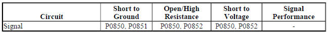
Typical Scan Tool Data
Park/Neutral Position Switch
.jpg)
Circuit/System Description
The transmission manual shift shaft switch assembly, also known as the transmission internal mode switch is a sliding contact switch attached to the manual shift shaft inside the transmission case. The park/neutral position switch is integrated into the transmission internal mode switch and connects to the transmission control module (TCM) lead-frame through a short wire harness. The park/neutral signal circuit uses the TCM as a pass-through connector only. The TCM provides the low reference circuit to the park/neutral position switch.
The Park/Neutral Signal is sent from the park/neutral switch directly to the Engine Control Module (ECM) and is used for engine start enable.
Conditions for Running the DTC
- Ignition voltage is between 8-18 V.
- Engine speed is 1000 RPM or greater.
- Runs continuously when above conditions are met.
Conditions for Setting the DTC
P0850 and P0851
- ECM detects the Park/Neutral switch signal equals 0 V (Park/Neutral) when the transmission internal mode switch reports a Drive range.
- Throttle position is 10 % or greater.
- Engine torque is 75 (55 lb ft) or greater.
- Vehicle speed is 10 km/h (6 mph) or greater.
- Above conditions must be met for 0.2 s.
P0852
ECM detects the Park/Neutral switch signal equals 12 V (In-Gear) when the IMS reports a Park/Neutral range for 0.2 s.
Action Taken When the DTC Sets
- DTCs P0850, P0851, and P0852 are Type C DTCs.
- ECM uses the transmission internal mode switch position, which is determined by the transmission control module and broadcast over GMLAN, for engine start-up.
Conditions for Clearing the DTC
DTCs P0850, P0851, and P0852 are Type C DTCs.
Reference Information
Schematic Reference
Automatic Transmission Controls Schematics (Encore, MH8 or MHB) , Automatic Transmission Controls Schematics (Trax, MH8 or MHB)
Connector End View Reference
WIRING SYSTEMS AND POWER MANAGEMENT - COMPONENT CONNECTOR END VIEWS - INDEX - ENCORE WIRING SYSTEMS AND POWER MANAGEMENT - COMPONENT CONNECTOR END VIEWS - INDEX - TRAX
Inline Harness Connector End Views (Encore) , Inline Harness Connector End Views (Trax)
Description and Operation
- Transmission General Description
- Electronic Component Description
- Transmission Component and System Description
Electrical Information Reference
- Circuit Testing
- Connector Repairs
- Testing for Intermittent Conditions and Poor Connections
- Wiring Repairs
DTC Type Reference
Powertrain Diagnostic Trouble Code (DTC) Type Definitions (LUV) , Powertrain Diagnostic Trouble Code (DTC) Type Definitions (2H0)
Scan Tool Reference
Control Module References for scan tool information
Special Tools
DT-48616-10 Adapter Harness
For equivalent regional tools, refer to Special Tools .
Circuit/System Verification
- Ignition ON.
- Verify that DTC P182E or P1915 is not set.
If any of the DTCs are set
Refer to DTC P182E or P1915.
If none of the DTCs are set
- Verify the range selector lever cable is adjusted properly. Refer to Range Selector Lever Cable Adjustment
- If the cable adjustment is not OK
Adjust, repair or replace as necessary.
- If the cable adjustment is OK
- Ignition ON.
- Verify the scan tool TCM Internal Mode Switch parameter matches the gear shift lever position while slowly moving the gear shift lever from Park through all gear ranges.
If any gear shift lever position does not match
Refer to DTC P182E or P1915.
If all gear positions match
- Verify the scan tool Park/Neutral Position Switch parameter displays Park/Neutral when in Park or Neutral and In-Gear when in Reverse or Drive.
If Park/Neutral or In Gear is not displayed
Refer to Circuit/System Testing.
If Park/Neutral and In Gear is displayed
- Operate the vehicle within the Conditions for Running the DTC. You may also operate the vehicle within the conditions that you observed from the Freeze Frame/Failure Records data.
- Verify the DTC does not set.
If the DTC sets
Refer to Circuit/System Testing.
If the DTC does not set
- All OK
Circuit/System Testing
NOTE: You must perform the Circuit/System Verification first.
- Ignition OFF, disconnect the X1 Q8 Control Solenoid Valve Assembly harness connector at the automatic transmission.
- Install the DT-48616-10 adapter harness to the vehicle harness connector.
NOTE: All testing in steps 3 through 5 will be performed at the DT-48616-10 adapter harness connector.
- Test for less than 5 ohms between the ground circuit terminal 2 and ground.
If 5 ohms or greater
- Ignition OFF.
- Test for less than 2 ohms in the ground circuit end to end.
- If 2 ohms or greater, repair the open/high resistance in the circuit.
- If less than 2 ohms, repair the open/high resistance in the ground connection.
If less than 5 ohms
- Ignition ON.
- Test for 11-13 V between signal circuit terminal 3 and ground.
If not between 11-13 V
- Ignition OFF, remove the harness connector at the K20 Engine Control Module.
- Test for infinite resistance between signal circuit terminal 3 and ground.
- If less than infinite resistance, repair the short to ground in the circuit.
- If infinite resistance.
- Test for less than 2 ohms in the signal circuit end to end.
- If 2 ohms or greater, repair the open/high resistance in the circuit.
- If less than 2 ohms, replace the K20 Engine Control Module.
If between 11-13 V
- Ignition OFF, disconnect the DT-48616-10 adapter harness from the vehicle wire harness.
- Remove the transmission control valve body cover.
- Connect the vehicle harness connector to the Q8 Control Solenoid Valve Assembly.
- Disconnect the B15 Transmission Internal Mode Switch X2 electrical connector from the Q8 Control Solenoid Valve Assembly.
- Ignition ON.
- Verify the scan tool ECM Park/Neutral Position Switch parameter displays In Gear.
If In Gear is not displayed
- Ignition OFF, disconnect the X1 harness connector at the Q8 Control Solenoid Valve Assembly.
- Install the DT-48616-10 adapter harness to the Q8 Control Solenoid Valve Assembly X1 connector.
- Test for infinite resistance between the DT-48616-10 adapter harness connector terminals 2 and 3.
- If less than infinite resistance, replace the Q8 Control Solenoid Valve Assembly.
- If infinite resistance, replace the K20 Engine Control Module.
- If In Gear is displayed
- Connect a 3A fused jumper between the Q8 Control Solenoid Valve Assembly X2 connector signal circuit terminal A and ground. Ignition ON.
- Verify the scan tool ECM Park/Neutral Position Switch parameter displays Park/Neutral.
If Park/Neutral is not displayed
- Ignition OFF, disconnect the X1 harness connector at the Q8 Control Solenoid Valve Assembly.
- Install the DT-48616-10 adapter harness to the Q8 Control Solenoid Valve Assembly X1 connector.
- Test for less than 2 ohms between adapter harness connector terminal 3 and the Q8 Control Solenoid Valve Assembly connector signal circuit terminal A.
- If 2 ohms or greater, replace the Q8 Control Solenoid Valve Assembly.
- If less than 2 ohms, replace the K20 Engine Control Module.
If Park/Neutral is displayed
- Replace the B15 Transmission Internal Mode Switch.
Repair Instructions
Perform the Diagnostic Repair Verification after completing the repair.
- Perform the Transmission Adaptive Values Learn following all transmission repairs.
- Range Selector Lever Cable Adjustment
- Control Valve Body Cover Replacement
- Manual Shift Detent Lever with Shaft Position Switch Assembly Replacement
- Control Valve Body Cover Replacement
- Control Module References - for Engine Control Module or Control Solenoid Valve Assembly replacement, programming and setup
