Chevrolet Trax: DTC P0340, P0341, P0365, OR P0366
Diagnostic Instructions
- Perform the Diagnostic System Check - Vehicle prior to using this diagnostic procedure.
- Review Strategy Based Diagnosis for an overview of the diagnostic approach.
- Diagnostic Procedure Instructions provides an overview of each diagnostic category.
DTC Descriptors
DTC P0340
Intake Camshaft Position Sensor Circuit
DTC P0341
Intake Camshaft Position Sensor Performance
DTC P0365
Exhaust Camshaft Position Sensor Circuit
DTC P0366
Exhaust Camshaft Position Sensor Performance
Diagnostic Fault Information
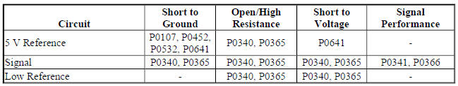
Circuit/System Description
The camshaft position sensors each have 3 circuits consisting of an engine control module (ECM) supplied 5 V reference circuit, low reference circuit, and an output signal circuit. The camshaft position sensor is an internally magnetic biased digital output integrated circuit sensing device. The sensor detects magnetic flux changes of the teeth and slots of a 4-tooth reluctor wheel attached to the camshaft. As each reluctor wheel tooth rotates past the camshaft position sensor, the resulting change in the magnetic field is used by the sensor electronics to produce a digital output pulse. The sensor returns a digital ON/OFF DC voltage pulse of varying frequency with 4 varying width output pulses per camshaft revolution that represent an image of the camshaft reluctor wheel. The frequency of the camshaft position sensor output depends on the velocity of the camshaft.
The ECM decodes the narrow and wide tooth pattern to identify camshaft position. This information is then used to determine the optimum ignition and injection points of the engine. The ECM uses the exhaust camshaft position sensor to determine injector and ignition system synchronization. The intake and exhaust camshaft position sensors are also used to determine camshaft to crankshaft relationship. The ECM also uses camshaft position sensor output information to determine the camshaft relative position to the crankshaft to control camshaft phasing and limp-home operation.
Conditions for Running the DTC
P0340 or P0365 Condition 1
- The starter is engaged and the engine control module detects camshaft position sensor pulses.
OR
- DTCs P0101, P0102, and P0103 are not set.
- The airflow into the engine is greater than 2 g/s.
Condition 2
- The engine is running and the starter is not engaged.
- DTC P0651 is not set.
Condition 3
- The crankshaft is synchronized.
- The starter is engaged.
- DTC P0335, P0336, P0641, or P0651 are not set.
Condition 4
- The crankshaft is synchronized.
- DTC P0335, P0336, P0641, or P0651 are not set.
P0341 or P0366 Condition 1
- The crankshaft is synchronized.
- The starter is engaged.
- DTC P0335, P0336, P0641, or P0651 are not set.
Condition 2
- The crankshaft is synchronized.
- DTC P0335, P0336, P0641, or P0651 are not set.
The DTCs run continuously once the above conditions are met.
Conditions for Setting the DTC
P0340 or P0365 Condition 1
The ECM does not detect a camshaft position sensor pulse for greater than 5.5 s or greater than 4.0 s since the time the starter has been engaged.
Condition 2
The ECM detects less than 4 camshaft position sensor pulses for greater than 3.0 s.
Condition 3
The ECM does not detect a camshaft position sensor pulse during the first 2 engine revolutions.
Condition 4
The ECM does not detect a camshaft position sensor pulse during 200 engine revolutions
P0341 or P0366 Condition 1
The ECM detects less than 4 or greater than 6 camshaft position sensor pulses during the first 2 engine revolutions.
Condition 2
The ECM detects less than 398 or greater than 402 camshaft position sensor pulses during 200 engine revolutions.
Action Taken When the DTC Sets
- DTCs P0340, P0341, P0365, and P0366 are Type B DTCs.
- The camshaft position actuator is commanded to the Home or Parked position.
- The ignition system defaults to a failed camshaft position sensor limp home mode.
Conditions for Clearing the MIL/DTC
DTCs P0340, P0341, P0365, and P0366 are Type B DTCs.
Diagnostic Aids
- With a DTC set, the engine may crank for an extended period of time at start-up
- The exhaust camshaft position sensor is used for injector and ignition system synchronization. A stalling condition will occur if the camshaft positionsensor signal is intermittent and a DTC may not set. Inspect the intake and exhaust camshaft position sensor circuits for poor connections
Reference Information
Schematic Reference
Engine Controls Schematics (Encore) , Engine Controls Schematics (Trax)
Connector End View Reference
WIRING SYSTEMS AND POWER MANAGEMENT - COMPONENT CONNECTOR END VIEWS - INDEX - ENCORE WIRING SYSTEMS AND POWER MANAGEMENT - COMPONENT CONNECTOR END VIEWS - INDEX - TRAX
Description and Operation
Electronic Ignition System Description
Electrical Information Reference
- Circuit Testing
- Connector Repairs
- Testing for Intermittent Conditions and Poor Connections
- Wiring Repairs
DTC Type Reference
Powertrain Diagnostic Trouble Code (DTC) Type Definitions (LUV) , Powertrain Diagnostic Trouble Code (DTC) Type Definitions (2H0)
Scan Tool Reference
Control Module References for scan tool information
Circuit/System Verification
- Ignition ON.
- Verify DTC P0641 or P0651 is not set.
- If any of the DTCs are set
Refer to DTC P0641, P0651, P0697, or P06A3 (ECM).
- If none of the DTCs are set
- Engine Running.
- Verify the scan tool parameters listed below increment:
- Exhaust Camshaft Position Active Counter
- Intake Camshaft Position Active Counter
- If any counter does not increment
Refer to Circuit/System Testing.
- If all counters increment
- Operate the vehicle within the Conditions for Running the DTC. You may also operate the vehicle within the conditions that you observed from the Freeze Frame/Failure Records data.
- Verify the DTC does not set.
- If the DTC sets
Refer to Circuit/System Testing.
- If the DTC does not set
- All OK.
Circuit/System Testing
- Ignition OFF and all vehicle systems OFF, disconnect the harness connector at the appropriate B23 Camshaft Position Sensor. It may take up to 2 minutes for all vehicle systems to power down.
- Test for less than 5 ohms between the low reference circuit terminal 2 and ground.
- If 5 ohms or greater
- Ignition OFF, disconnect the X2 harness connector at the K20 Engine Control Module.
- Test for less than 2 ohms in the low reference circuit end to end.
- If 2 ohms or greater, repair the open/high resistance in the circuit.
- If 2 ohms or less, replace the K20 Engine Control Module.
- If less than 5 ohms
- Ignition ON.
- Test for 4.8-5.2 V between the 5 V reference circuit terminal 1 and ground.
- If less than 4.8 V
- Ignition OFF, disconnect the X2 harness connector at the K20 Engine Control Module.
- Test for infinite resistance between the 5 V reference circuit and ground.
- If less than infinite resistance, repair the short to ground on the circuit.
- If infinite resistance.
- Test for less than 2 ohms in the 5 V reference circuit end to end.
- If 2 ohms or greater, repair the open/high resistance in the circuit.
- If less than 2 ohms , replace the K20 Engine Control Module.
- If greater than 5.2 V
- Ignition OFF, disconnect the X2 harness connector at the K20 Engine Control Module, ignition ON.
- Test for less than 1 V between the 5 V reference circuit and ground.
- If 1 V or greater, repair the short to voltage on the circuit.
- If less than 1 V, replace the K20 Engine Control Module.
- If between 4.8-5.2 V
- Test for 4.8-5.2 V between the signal circuit terminal 3 and ground.
- If less than 4.8 V
- Ignition OFF, disconnect the X2 harness connector at the K20 Engine Control Module.
- Test for infinite resistance between the signal circuit and ground.
- If less than infinite resistance, repair the short to ground on the circuit.
- If infinite resistance.
- Test for less than 2 ohms in the signal circuit end to end.
- If 2 ohms or greater, repair the open/high resistance in the circuit.
- If less than 2 ohms, replace the K20 Engine Control Module.
- If greater than 5.2 V
- Ignition OFF, disconnect the X2 harness connector at the K20 Engine Control Module, ignition ON.
- Test for less than 1 V between the signal circuit and ground.
- If 1 V or greater, repair the short to voltage on the circuit.
- If less than 1 V, replace the K20 Engine Control Module.
- If between 4.8-5.2 V
- Verify DTC P0341 or P0366 is not set.
- If any of the DTCs are set
Inspect for the conditions listed below:
- Excessive play or looseness of the B23 Camshaft Position Sensor or the reluctor wheel
- Improper installation of the B23 Camshaft Position Sensor
- Foreign material passing between the B23 Camshaft Position Sensor and the reluctor wheel
- Damaged reluctor wheel
- Excessive air gap between the B23 Camshaft Position Sensor and the reluctor wheel
- Engine oil for debris
- Timing chain, tensioner, and sprockets for wear or damage
- If any of the conditions above are found, repair as necessary.
- If all components test normal, test or replace the B23 Camshaft Position Sensor.
- If none of the DTCs are set
- Test or replace the B23 Camshaft Position Sensor.
Repair Instructions
Perform the Diagnostic Repair Verification after completing the repair.
- Camshaft Position Sensor Replacement
- Control Module References for engine control module replacement, programming, and setup
READ NEXT:
 DTC P0351-P0354, P2300, P2301, P2303, P2304, P2306, P2307, P2309, OR P2310
Diagnostic Instructions
Perform the Diagnostic System Check - Vehicle prior to using this
diagnostic procedure.
Review Strategy Based Diagnosis for an overview of the diagnostic
approach.
Dia
DTC P0420
Diagnostic Instructions
Perform the Diagnostic System Check - Vehicle prior to using this
diagnostic procedure.
Review Strategy Based Diagnosis for an overview of the diagnostic
approach.
Diag
DTC P0442
Diagnostic Instructions
Perform the Diagnostic System Check - Vehicle prior to using this
diagnostic procedure.
Review Strategy Based Diagnosis for an overview of the diagnostic
approach.
Diag
SEE MORE:
DTC P0850-P0852
Diagnostic Instructions
Perform the Diagnostic System Check - Vehicle prior to using this
diagnostic procedure.
Review Strategy Based Diagnosis for an overview of the diagnostic
approach.
Diagnostic Procedure Instructions provides an overview of each
diagnostic category.
DTC Descriptors
D
General Information - Encore And Trax
INTRODUCTION
ARROWS AND SYMBOLS
This service manual uses various symbols in order to describe different
service operations.
Fig. 1: Identifying Different Service Operations Symbols
ACRONYMS AND UNITS
Acronyms
Units
CUSTOMER CONCERN VERIFICATION SHEETS
The GM Customer Concern Verific
