Chevrolet Trax: DTC P0351-P0354, P2300, P2301, P2303, P2304, P2306, P2307, P2309, OR P2310
Diagnostic Instructions
- Perform the Diagnostic System Check - Vehicle prior to using this diagnostic procedure.
- Review Strategy Based Diagnosis for an overview of the diagnostic
approach.
Diagnostic Procedure Instructions provides an overview of each diagnostic category.
DTC Descriptors
DTC P0351
Ignition Coil 1 Control Circuit
DTC P0352
Ignition Coil 2 Control Circuit
DTC P0353
Ignition Coil 3 Control Circuit
DTC P0354
Ignition Coil 4 Control Circuit
DTC P2300
Ignition Coil 1 Control Circuit Low Voltage
DTC P2301
Ignition Coil 1 Control Circuit High Voltage
DTC P2303
Ignition Coil 2 Control Circuit Low Voltage
DTC P2304
Ignition Coil 2 Control Circuit High Voltage
DTC P2306
Ignition Coil 3 Control Circuit Low Voltage
DTC P2307
Ignition Coil 3 Control Circuit High Voltage
DTC P2309
Ignition Coil 4 Control Circuit Low Voltage
DTC P2310
Ignition Coil 4 Control Circuit High Voltage
Diagnostic Fault Information
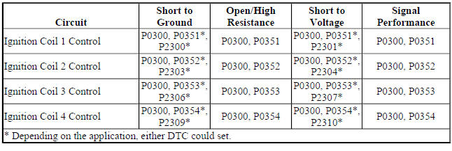
Circuit/System Description
The ignition system on this engine uses an ignition coil module. The engine control module (ECM) controls the spark event for each cylinder through the individual ignition coil control circuits. When the ECM commands the ignition control circuit ON, electrical current will flow through the primary winding of the ignition coil, creating a magnetic field. When a spark event is requested, the ECM will command the ignition control circuit OFF, interrupting current flow through the primary winding. The magnetic field created by the primary winding will collapse across the secondary coil windings, producing a high voltage across the spark plug electrodes. The ECM uses information from the crankshaft position sensor, and the camshaft position sensor for sequencing and timing of the spark events. The ECM monitors each ignition control circuit for improper voltage levels.
Conditions for Running the DTC
- The engine is running.
- Ignition voltage is greater than 5 V.
The DTCs run continuously when the above conditions are met.
Conditions for Setting the DTC
The engine control module detects that the voltage command state of the driver and the actual state of the control circuit do not match.
Action Taken When the DTC Sets
DTCs P0351, P0352, P0353, P0354, P2300, P2301, P2303, P2304, P2306, P2307, P2309, or P2310 are Type B DTCs.
Conditions for Clearing the MIL/DTC
DTCs P0351, P0352, P0353, P0354, P2300, P2301, P2303, P2304, P2306, P2307, P2309, or P2310 are Type B DTCs.
Reference Information
Schematic Reference
Engine Controls Schematics (Encore) , Engine Controls Schematics (Trax)
Connector End View Reference
WIRING SYSTEMS AND POWER MANAGEMENT - COMPONENT CONNECTOR END VIEWS - INDEX - ENCORE WIRING SYSTEMS AND POWER MANAGEMENT - COMPONENT CONNECTOR END VIEWS - INDEX - TRAX
Description and Operation
Electronic Ignition System Description
Electrical Information Reference
- Circuit Testing
- Connector Repairs
- Testing for Intermittent Conditions and Poor Connections Wiring Repairs
DTC Type Reference
Powertrain Diagnostic Trouble Code (DTC) Type Definitions (LUV) , Powertrain Diagnostic Trouble Code (DTC) Type Definitions (2H0)
Scan Tool Reference
Control Module References for scan tool information
Circuit/System Verification
- Engine Running.
- Verify the scan tool parameters listed below do not display Malfunction:
- Ignition Coil 1-4 Control Circuit High Voltage Test Status
- Ignition Coil 1-4 Control Circuit Low Voltage Test Status
- Ignition Coil 1-4 Control Circuit Open Test Status
- If Malfunction is displayed
Refer to Circuit/System Testing.
- If Malfunction is not displayed
- Operate the vehicle within the Conditions for Running the DTC. You may also operate the vehicle within the conditions that you observed from the Freeze Frame/Failure Records data.
- Verify the DTC does not set.
- If the DTC sets
Refer to Circuit/System Testing.
- If the DTC does not set
- All OK.
Circuit/System Testing
- Ignition OFF and all vehicle systems OFF, disconnect the harness connector at the K35 Ignition Coil Module.
- Remove the fuel injector fuse.
- Connect a DMM between the appropriate K35 Ignition Coil Module control circuit listed below and ground. Set the DMM to the DC Hz scale and utilize the Min-Max function:
- Ignition Coil 1 terminal D
- Ignition Coil 2 terminal E
- Ignition Coil 3 terminal F
- Ignition Coil 4 terminal G
- Verify the DMM displays greater than 1.5 Hz while cranking the engine.
- If less than 1.5 Hz
- Ignition OFF, disconnect the X2 harness connector at the K20 Engine Control Module.
- Test for infinite resistance between the control circuit and ground.
- If less than infinite resistance, repair the short to ground on the circuit.
- If infinite resistance
- Test for less than 2 ohms in the control circuit end to end.
- If 2 ohms or greater, repair the open/high resistance in the circuit.
- If less than 2 ohms
- Ignition ON.
- Test for less than 1 V between the control circuit and ground.
- If 1 V or greater, repair the short to voltage on the circuit.
- If less than 1 V, replace the K20 Engine Control Module.
- If greater than 1.5 Hz
- Replace the K35 Ignition Coil Module.
Repair Instructions
Perform the Diagnostic Repair Verification after completing the repair.
- Ignition Coil Replacement
- Control Module References for engine control module replacement, programming, and setup
READ NEXT:
 DTC P0420
Diagnostic Instructions
Perform the Diagnostic System Check - Vehicle prior to using this
diagnostic procedure.
Review Strategy Based Diagnosis for an overview of the diagnostic
approach.
Diag
DTC P0442
Diagnostic Instructions
Perform the Diagnostic System Check - Vehicle prior to using this
diagnostic procedure.
Review Strategy Based Diagnosis for an overview of the diagnostic
approach.
Diag
DTC P0443, P0458, OR P0459
Diagnostic Instructions
Perform the Diagnostic System Check - Vehicle prior to using this
diagnostic procedure.
Review Strategy Based Diagnosis for an overview of the diagnostic
approach.
Diag
SEE MORE:
Securing Child Restraints (Front Passenger Seat - U.S. and Canada)
This vehicle has airbags. A rear
seat is a safer place to secure a
forward-facing child restraint. See
Where to Put the Restraint
Never put a rear-facing child seat in
the front. This is because the risk to
the rear-facing child is so great,
if the airbag deploys.
Warning
A child in a rear-facing ch
DTC P0033-P0035
Diagnostic Instructions
Perform the Diagnostic System Check - Vehicle prior to using this
diagnostic procedure.
Review Strategy Based Diagnosis for an overview of the diagnostic
approach.
Diagnostic Procedure Instructions provides an overview of each
diagnostic category.
DTC Descriptors
D
