Chevrolet Trax: DTC P0335 OR P0336
Diagnostic Instructions
- Perform the Diagnostic System Check - Vehicle prior to using this diagnostic procedure.
- Review Strategy Based Diagnosis for an overview of the diagnostic approach.
- Diagnostic Procedure Instructions provides an overview of each diagnostic category.
DTC Descriptors
DTC P0335
Crankshaft Position Sensor Circuit
DTC P0336
Crankshaft Position Sensor Performance
Diagnostic Fault Information
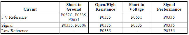
Circuit/System Description
The crankshaft position sensor circuits consist of an engine control module (ECM) supplied 5 V reference circuit, low reference circuit, and an output signal circuit. The crankshaft position sensor is an internally magnetic biased digital output integrated circuit sensing device. The sensor detects magnetic flux changes of the teeth and slots of a 58-tooth reluctor wheel on the crankshaft. Each tooth on the reluctor wheel is spaced at 60- tooth spacing, with 2 missing teeth for the reference gap. The crankshaft position sensor produces an ON/OFF DC voltage of varying frequency, with 58 output pulses per crankshaft revolution. The frequency of the crankshaft position sensor output depends on the velocity of the crankshaft. The crankshaft position sensor sends a digital signal, which represents an image of the crankshaft reluctor wheel, to the ECM as each tooth on the wheel rotates past the crankshaft position sensor. The ECM uses each crankshaft position signal pulse to determine crankshaft speed and decodes the crankshaft reluctor wheel reference gap to identify crankshaft position. This information is then used to determine the optimum ignition and injection points of the engine.
The ECM also uses crankshaft position sensor output information to determine the camshaft relative position to the crankshaft, to control camshaft phasing, and to detect cylinder misfire.
Conditions for Running the DTC
P0335 Condition 1
- The starter is engaged and the engine control module detects camshaft position (CMP) sensor pulses.
OR
- DTCs P0101, P0102 and P0103 are not set.
AND
- The airflow into the engine is greater than 2 g/s.
Condition 2
- The engine is running and the starter is not engaged.
- DTC P0651 is not set.
Condition 3
- The engine is running or the starter is engaged.
- DTCs P0365, P0366, P0641, or P0651 are not set.
P0336 Condition 1
- The airflow into the engine is greater than 2 g/s.
- Engine speed is greater than 450 RPM.
- DTCs P0335 or P0651 are not set.
Condition 2
- The engine is running and the starter is not engaged.
- DTC P0651 is not set.
Condition 3
- The starter is engaged and the engine control module detects camshaft position (CMP) sensor pulses.
OR
- DTCs P0101, P0102, and P0103 are not set.
- The airflow into the engine is greater than 2 g/s.
Condition 4
- The engine is running or the starter is engaged.
- DTCs P0365, P0366, P0641, or P0651 are not set.
The DTCs run continuously once the above conditions are met.
Conditions for Setting the DTC
P0335 Condition 1
The ECM does not detect a crankshaft position sensor pulse for greater than 4 s.
Condition 2
The ECM does not detect a crankshaft position sensor pulse for greater than 0.1 s.
Condition 3
The ECM does not detect a crankshaft position sensor pulse for 2 out of 10 engine revolutions.
P0336 Condition 1
The ECM detects that 10 or more crankshaft resynchronization have occurred within 10 s.
Condition 2
The ECM does not detect the synchronization gap on the reluctor wheel for greater than 0.4 s.
Condition 3
The ECM does not detect the synchronization gap on the reluctor wheel for greater than 1.5 s after the starter was engaged.
Condition 4
The ECM detects less than 51 or greater than 65 crankshaft position sensor pulses during 1 engine revolution for 8 out of 10 engine revolutions.
Action Taken When the DTC Sets
- DTCs P0335 and P0336 are Type B DTCs.
- The camshaft position sensor is used to determine engine position.
- The camshaft actuators are commanded to the parked position.
Conditions for Clearing the DTC
DTCs P0335 and P0336 are Type B DTCs.
Reference Information
Schematic Reference
Engine Controls Schematics (Encore) , Engine Controls Schematics (Trax)
Connector End View Reference
WIRING SYSTEMS AND POWER MANAGEMENT - COMPONENT CONNECTOR END VIEWS - INDEX - ENCORE WIRING SYSTEMS AND POWER MANAGEMENT - COMPONENT CONNECTOR END VIEWS - INDEX - TRAX
Description and Operation
Electronic Ignition System Description
Electrical Information Reference
- Circuit Testing
- Connector Repairs
- Testing for Intermittent Conditions and Poor Connections
- Wiring Repairs
DTC Type Reference
Powertrain Diagnostic Trouble Code (DTC) Type Definitions (LUV) , Powertrain Diagnostic Trouble Code
(DTC) Type Definitions (2H0) Scan Tool Reference
Control Module References for scan tool information
Circuit/System Verification
- Ignition ON.
- Verify DTC P0651 is not set.
- If the DTC is set
Refer to DTC P0641, P0651, P0697, or P06A3 (ECM).
- If the DTC is not set
- Engine Running.
- Verify the scan tool Crankshaft Position Active Counter parameter increments.
- If the counter does not increment
Refer to Circuit/System Testing.
- If the counter increments
- Verify the scan tool Crankshaft Position Resync Counter parameter displays 0 counts and the engine does not stumble or stall while moving the related harness/connectors of the B26 Crankshaft Position Sensor.
- If greater than 0 counts and the engine stumbles or stalls
Refer to Circuit/System Testing.
- If 0 counts and the engine does not stumble or stall
- Operate the vehicle within the Conditions for Running the DTC. You may also operate the vehicle within the conditions that you observed from the Freeze Frame/Failure Records data.
- Verify the DTC does not set.
- If the DTC sets
Refer to Circuit/System Testing.
- If the DTC does not set
- All OK.
Circuit/System Testing
- Ignition OFF and all vehicle systems OFF, disconnect the harness connector at the B26 Crankshaft Position Sensor. It may take up to 2 minutes for all vehicle systems to power down.
- Test for less than 5 ohms between the low reference circuit terminal 2 and ground.
- If 5 ohms or greater
- Ignition OFF, disconnect the X2 harness connector at the K20 Engine Control Module.
- Test for less than 2 ohms in the low reference circuit end to end.
- If 2 ohms or greater, repair the open/high resistance in the circuit.
- If 2 ohms or less, replace the K20 Engine Control Module.
- If less than 5 ohms
- Ignition ON.
- Test for 4.8-5.2 V between the 5 V reference circuit terminal 1 and ground.
- If less than 4.8 V
- Ignition OFF, disconnect the X2 harness connector at the K20 Engine Control Module.
- Test for infinite resistance between the 5 V reference circuit and ground.
- If less than infinite resistance, repair the short to ground on the circuit.
- If infinite resistance
- Test for less than 2 ohms in the 5 V reference circuit end to end.
- If 2 ohms or greater, repair the open/high resistance in the circuit.
- If less than 2 ohms, replace the K20 Engine Control Module.
- If greater than 5.2 V
- Ignition OFF, disconnect the X2 harness connector at the K20 Engine Control Module, ignition ON.
- Test for less than 1 V between the 5 V reference and ground.
- If 1 V or greater, repair the short to voltage on the circuit.
- If less than 1 V, replace the K20 Engine Control Module.
- If between 4.8-5.2 V
- Test for 4.8-5.2 V between the signal circuit terminal 3 and ground.
- If less than 4.8 V
- Ignition OFF, disconnect the X2 harness connector at the K20 Engine Control Module.
- Test for infinite resistance between the signal circuit and ground.
- If less than infinite resistance, repair the short to ground on the circuit.
- If infinite resistance
- Test for less than 2 ohms in the signal circuit end to end.
- If 2 ohms or greater, repair the open/high resistance in the circuit.
- If less than 2 ohms, replace the K20 Engine Control Module.
- If greater than 5.2 V
- Ignition OFF, disconnect the X2 harness connector at the K20 Engine Control Module, ignition ON.
- Test for less than 1 V between the signal circuit and ground.
- If 1 V or greater, repair the short to voltage on the circuit.
- If less than 1 V, replace the K20 Engine Control Module.
- If between 4.8-5.2 V
- Ignition OFF, connect a 3 A fused jumper wire to the signal circuit terminal 3, ignition ON.
NOTE: Additional DTCs may set when performing this test.
- Verify the scan tool Crankshaft Position Sensor Active Counter parameter increments while rapidly tapping the fused jumper wire end to ground.
- If the counter does not increment
Replace the K20 Engine Control Module.
- If the counter increments
- Verify DTC P0336 is not set.
- If the DTC is set
Inspect for the conditions listed below:
- Excessive play or looseness of the B26 Crankshaft Position Sensor or the reluctor wheel
- Improper installation of the B26 Crankshaft Position Sensor
- Foreign material passing between the B26 Crankshaft Position Sensor and the reluctor wheel Damaged reluctor wheel
- Excessive air gap between the B26 Crankshaft Position Sensor and the reluctor wheel
- Engine oil for debris
- Timing chain, tensioner, and sprockets for wear or damage
- If any of the conditions above are found, repair as necessary.
- If all components test normal, test or replace the B26 Crankshaft Position Sensor.
- If the DTC is not set
- Test or replace the B26 Crankshaft Position Sensor.
Repair Instructions
Perform the Diagnostic Repair Verification after completing the repair.
- Crankshaft Position Sensor Replacement
- Control Module References for engine control module replacement, programming, and setup
READ NEXT:
 DTC P0340, P0341, P0365, OR P0366
Diagnostic Instructions
Perform the Diagnostic System Check - Vehicle prior to using this
diagnostic procedure.
Review Strategy Based Diagnosis for an overview of the diagnostic
approach.
Diag
DTC P0351-P0354, P2300, P2301, P2303, P2304, P2306, P2307, P2309, OR P2310
Diagnostic Instructions
Perform the Diagnostic System Check - Vehicle prior to using this
diagnostic procedure.
Review Strategy Based Diagnosis for an overview of the diagnostic
approach.
Dia
DTC P0420
Diagnostic Instructions
Perform the Diagnostic System Check - Vehicle prior to using this
diagnostic procedure.
Review Strategy Based Diagnosis for an overview of the diagnostic
approach.
Diag
SEE MORE:
Traction control/stability control indicator alfunction
Diagnostic Instructions
Perform the Diagnostic System Check - Vehicle prior to using this
diagnostic procedure.
Review Strategy Based Diagnosis for an overview of the diagnostic
approach.
Diagnostic Procedure Instructions provides an overview of each
diagnostic category.
Diagnostic Fault
Instrument panel retainer replacement - right side (encore)
Removal Procedure
Remove the right instrument panel outer air outlet. Refer to Instrument
Panel Outer Air Outlet
Replacement (Encore) .
Remove the right instrument panel outer trim cover. Refer to Instrument
Panel Outer Trim Cover
Replacement (Encore).
Remove the instrument panel upper com
