Chevrolet Trax: DTC P0117, P0118, OR P0119
Diagnostic Instructions
- Perform the Diagnostic System Check - Vehicle prior to using this diagnostic procedure.
- Review Strategy Based Diagnosis for an overview of the diagnostic approach.
- Diagnostic Procedure Instructions provides an overview of each diagnostic category.
DTC Descriptors
DTC P0117
Engine Coolant Temperature (ECT) Sensor Circuit Low Voltage
DTC P0118
Engine Coolant Temperature (ECT) Sensor Circuit High Voltage
DTC P0119
Engine Coolant Temperature (ECT) Sensor Circuit Intermittent
Diagnostic Fault Information
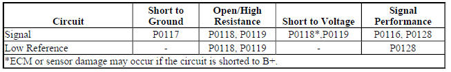
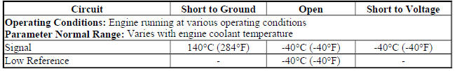
Typical Scan Tool Data
ECT Sensor
Circuit/System Description
The engine coolant temperature (ECT) sensor is a variable resistor that measures the temperature of the engine coolant. The engine control module (ECM) supplies 5 V to the ECT sensor signal circuit and a ground for the low reference circuit. This diagnostic checks for an open, short to ground or an intermittent circuit condition between the ECM and ECT sensor.
Conditions for Running the DTC
P0117
- The ignition is ON.
OR
- The engine is running for greater than 10 s.
OR
- The engine run time is less than 10 s when the intake air temperature (IAT) is colder than 50ºC (122ºF).
- This DTC runs continuously within the enabling conditions.
P0118
- The ignition is ON.
OR
- The engine is running for greater than 10 s.
OR
- The engine run time is less than 10 s when the IAT is warmer than 0ºC (32ºF).
- This DTC runs continuously within the enabling conditions.
P0119
- This DTC runs continuously within the enabling conditions.
Conditions for Setting the DTC
P0117
The ECM detects that the ECT is warmer than 149ºC (300ºF) for greater than 5 s.
P0118
The ECM detects that the ECT is colder than -39ºC (-38ºF) for greater than 5 s.
P0119
The ECM detects that the ECT is intermittent or has abruptly changed for greater than 4 seconds.
Action Taken When the DTC Sets
- DTC P0117, P0118 or P0119 are a Type B DTC.
- The cooling fans will be commanded ON.
- The Engine Coolant Temperature Gauge is inoperative.
- The AC compressor will be commanded OFF.
Conditions for Clearing the DTC
DTC P0117, P0118 or P0119 are a Type B DTC.
Reference Information
Schematic Reference
Engine Controls Schematics (Encore) , Engine Controls Schematics (Trax)
Connector End View Reference
WIRING SYSTEMS AND POWER MANAGEMENT - COMPONENT CONNECTOR END VIEWS - INDEX - ENCORE WIRING SYSTEMS AND POWER MANAGEMENT - COMPONENT CONNECTOR END VIEWS - INDEX - TRAX
Electrical Information Reference
- Circuit Testing
- Connector Repairs
- Testing for Intermittent Conditions and Poor Connections
- Wiring Repairs
DTC Type Reference
Powertrain Diagnostic Trouble Code (DTC) Type Definitions (LUV) , Powertrain Diagnostic Trouble Code (DTC) Type Definitions (2H0)
Scan Tool Reference
Control Module References for scan tool information
Circuit/System Verification
- Ignition ON.
- Verify the scan tool ECT Sensor parameter is between -39 to + 120ºC (-38 to +248ºF) and changes with engine run time.
- If not between -39 to + 120ºC (-38 to +248ºF) or does not change
Refer to Circuit/System Testing.
- If between -39 to + 120ºC (-38 to +248ºF) and changes
- Operate the vehicle within the Conditions for Running the DTC. You may also operate the vehicle within the conditions that you observed from the Freeze Frame/Failure Records data.
- Verify the DTC does not set.
- If the DTC sets
Refer to Circuit/System Testing.
- If the DTC does not set
- All OK.
Circuit/System Testing
- Ignition OFF and all vehicle systems OFF, disconnect the harness connector at the B34 Engine Coolant Temperature Sensor. It may take up to 2 minutes for all vehicle systems to power down.
- Test for less than 5 ohms between the low reference circuit terminal 2 and ground.
- If 5 ohms or greater
- Ignition OFF, disconnect the harness connector at the K20 Engine Control Module.
- Test for less than 2 ohms in the low reference circuit end to end.
- If 2 ohms or greater, repair the open/high resistance in the circuit.
- If less than 2 ohms, replace the K20 Engine Control Module.
- If less than 5 ohms
- Ignition ON.
- Verify the scan tool ECT Sensor parameter is colder than -39ºC (-38ºF).
If warmer than -39ºC (-38ºF)
- Ignition OFF, disconnect the harness connector at the K20 Engine Control Module.
- Test for infinite resistance between the signal circuit terminal 1 and ground.
- If less than infinite resistance, repair the short to ground on the circuit.
- If infinite resistance, replace the K20 Engine Control Module.
- If colder than -39ºC (-38ºF)
- Install a 3 A fused jumper wire between the signal circuit terminal 1 and the low reference circuit terminal 2.
- Verify the scan tool ECT sensor parameter is warmer than 137ºC (280ºF).
- If colder than 137ºC (280ºF)
- Ignition OFF, remove the jumper wire, disconnect the harness connector at the K20 Engine Control Module, ignition ON.
- Test for less than 1 V between the signal circuit and ground.
- If 1 V or greater, repair the short to voltage on the circuit.
- If less than 1 V
- Ignition OFF.
- Test for less than 2 ohms in the signal circuit end to end.
- If 2 ohms or greater, repair the open/high resistance in the circuit.
- If less than 2 ohms, replace the K20 Engine Control Module.
- If warmer than 137ºC (280ºF)
- Test or replace the B34 Engine Coolant Temperature Sensor.
Component Testing
- Ignition OFF, disconnect the harness connector at the B34 Engine Coolant Temperature Sensor.
- Test the ECT sensor by varying the sensor temperature while monitoring the sensor resistance. Compare the readings with the Temperature Versus Resistance table. The resistance values should be in range of the table values.
- If not within the specified range
Replace the B34 Engine Coolant Temperature Sensor.
- If within the specified range
- Test for infinite resistance between each terminal and the sensor housing.
- If less than infinite resistance
Replace the B34 Engine Coolant Temperature Sensor.
- If infinite resistance
- All OK.
Repair Instructions
Perform the Diagnostic Repair Verification after completing the repair.
- Engine Coolant Temperature Sensor Replacement (Water Outlet) , Engine Coolant Temperature Sensor Replacement (Radiator)
- Engine Control Module Replacement engine control module replacement, programming, and setup
READ NEXT:
 DTC P0121-P0123, P0222, P0223, OR P2135
Diagnostic Instructions
Perform the Diagnostic System Check - Vehicle prior to using this
diagnostic procedure.
Review Strategy Based Diagnosis for an overview of the diagnostic
approach.
Diag
DTC P0128
Diagnostic Instructions
Perform the Diagnostic System Check - Vehicle prior to using this
diagnostic procedure.
Review Strategy Based Diagnosis for an overview of the diagnostic
approach.
Diag
DTC P0131, P0132, P0134, P0137, P0138, OR P0140 (LUV)
Diagnostic Instructions
Perform the Diagnostic System Check - Vehicle prior to using this
diagnostic procedure.
Review Strategy Based Diagnosis for an overview of the diagnostic
approach.
Diag
SEE MORE:
Diagnostic Information and Procedures
STRATEGY BASED DIAGNOSIS
The goal of Strategy Based Diagnosis is to provide guidance when you create a
plan of action for each specific
diagnostic situation. Following a similar plan for each diagnostic situation,
you will achieve maximum
efficiency when you diagnose and repair vehicles. Although
Symptoms - automatic transmission
NOTE: Use the symptom tables only if the following conditions are
met:
Refer to Diagnostic Starting Point - Vehicle .
There are no DTCs set.
The control modules can communicate via the serial data link.
Review the system operation in order to familiarize yourself with the
system functions. Re
