Chevrolet Trax: DTC P0121-P0123, P0222, P0223, OR P2135
Diagnostic Instructions
- Perform the Diagnostic System Check - Vehicle prior to using this diagnostic procedure.
- Review Strategy Based Diagnosis for an overview of the diagnostic approach.
- Diagnostic Procedure Instructions provides an overview of each diagnostic category.
DTC Descriptors
DTC P0121
Throttle Position Sensor 1 Performance
DTC P0122
Throttle Position Sensor 1 Circuit Low Voltage
DTC P0123
Throttle Position Sensor 1 Circuit High Voltage
DTC P0222
Throttle Position Sensor 2 Circuit Low Voltage
DTC P0223
Throttle Position Sensor 2 Circuit High Voltage
DTC P2135
Throttle Position Sensors 1-2 Not Plausible
Diagnostic Fault Information
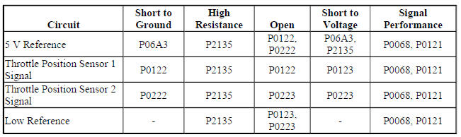
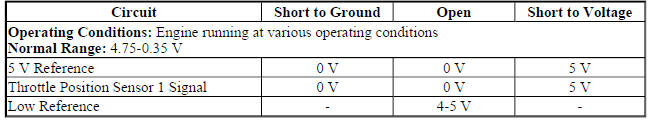
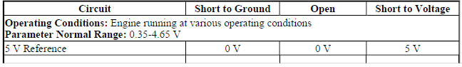
Typical Scan Tool Data
Throttle Position Sensor 1
Throttle Position Sensor 2

Circuit/System Description
The throttle body assembly contains 2 throttle position sensors. The throttle position sensors are mounted to the throttle body assembly and are not serviceable. The throttle position sensors provide a signal voltage that changes relative to throttle blade angle. The engine control module (ECM) supplies the throttle position sensors with a common 5 V reference circuit, a common low reference circuit, and two independent signal circuits.
The throttle position sensors have opposite functionality. throttle position sensor 1 signal voltage decreases and throttle position sensor 2 signal voltage increases as the accelerator pedal increases to wide open throttle (WOT).
Conditions for Running the DTC
P0122, P0123, P0222, and P0223
- DTC P06A3 is not set.
- The run/crank or powertrain relay voltage is greater than 6 V and reduced power is not active.
- The ignition is ON or the engine is operating.
- DTC P0122, P0123, P0222, P0223 run continuously when the above conditions are met.
P0121
- No Active or Pending DTCs.
- The engine speed is between 400-7,000 RPM.
- The engine coolant temperature (ECT) is between -7 to +125ºC (19-257ºF).
- The intake air temperature (IAT) is between -20 to +125ºC (-4 to +257ºF).
- DTC P0121 runs continuously when the above conditions are met.
P0121
- No Active or Pending DTCs.
- The engine speed is between 400-7,000 RPM.
- The engine coolant temperature (ECT) is between -7 to +125ºC (19-257ºF).
- The intake air temperature (IAT) is between -20 to +125ºC (-4 to +257ºF).
- DTC P0121 runs continuously when the above conditions are met.
P2135
- DTC P0122, P0123, P0222, P0223, or P06A3 is not set.
- The run/crank or powertrain relay voltage is greater than 6 V and reduced power is not active.
- The ignition is ON or the engine is operating.
- DTC P2135 runs continuously when the above conditions are met.
Conditions for Setting the DTC
P0121
The ECM detects the throttle position sensor is stuck within range for greater than 1 s.
P0122
The ECM detects the throttle position sensor 1 voltage is less than 0.325 V for greater than 1 s.
P0123
The ECM detects the throttle position sensor 1 voltage is greater than 4.75 V for greater than 1 s.
P0222
The ECM detects that the throttle position sensor 2 voltage is less than 0.25 V for greater than 1 s.
P0223
The ECM detects the throttle position sensor 2 voltage is greater than 4.59 V for greater than 1 s.
P2135
The ECM detects the difference between the throttle position sensor 1 and throttle position sensor 2 exceeds a predetermined value for greater than 1 s.
Action Taken When the DTC Sets
- DTC P0122, P0123, P0222, P0223, and P2135 are Type A DTCs.
- DTC P0121 is a Type B DTC.
- The ECM commands the TAC system to operate in the Reduced Engine Power mode.
- A message center or an indicator displays Reduced Engine Power.
- Under certain conditions the control module commands the engine OFF.
Conditions for Clearing the MIL/DTC
- DTCs P0122, P0123, P0222, P0223, and P2135 are Type A DTCs.
- DTC P0121 is a Type B DTC
Diagnostic Aids
- A high resistance condition on the throttle position and throttle actuator control circuits could cause a DTC to set.
- If the accelerator pedal is pressed to the wide open throttle position, the throttle blade angle or Throttle Position angle is limited to less than 40 percent.
Reference Information
Schematic Reference
Engine Controls Schematics (Encore) , Engine Controls Schematics (Trax)
Connector End View Reference
WIRING SYSTEMS AND POWER MANAGEMENT - COMPONENT CONNECTOR END VIEWS - INDEX - ENCORE WIRING SYSTEMS AND POWER MANAGEMENT - COMPONENT CONNECTOR END VIEWS - INDEX - TRAX
Description and Operation
Throttle Actuator Control (TAC) System Description
Electrical Information Reference
- Circuit Testing
- Connector Repairs
- Testing for Intermittent Conditions and Poor Connections
- Wiring Repairs
DTC Type Reference
Powertrain Diagnostic Trouble Code (DTC) Type Definitions (LUV) , Powertrain Diagnostic Trouble Code (DTC) Type Definitions (2H0)
Scan Tool Reference
Control Module References for scan tool information
Circuit/System Verification
- Ignition ON.
- If you were sent here from DTC P0068, P0101, P0106, or P1101 refer to Circuit/System Testing.
- Verify that DTC P0641, P0651, P0697, or P06A3 is not set.
- If any of the DTCs are set
Refer to DTC P0641, P0651, P0697, or P06A3 (ECM) for further diagnosis.
- If none of the DTCs are set
- Verify the scan tool Throttle Body Idle Airflow Compensation parameter is less than 90 %.
- 90 % or greater
Refer to Throttle Body Inspection and Cleaning .
- If less than 90 %
- Verify the scan tool Throttle Position Sensor 1 and Throttle Position Sensor 2 voltage parameters are between 1.0-4.0 V and change with accelerator pedal input.
- If not between 1.0-4.0 V or does not change
Refer to Circuit/System Testing
- If between 1.0-4.0 V and changes
- Verify the scan tool Throttle Position Sensor 1 and 2 Agree/Disagree parameter displays Agree while performing the Throttle Sweep Test with a scan tool.
- If Disagree
Refer to Circuit/System Testing
- If Agree
- Determine the current vehicle testing altitude.
- Verify the scan tool MAP Sensor pressure parameter is within range specified in the Altitude Versus Barometric Pressure table.
- The MAP Sensor pressure is not in range
Refer to DTC P0106.
- The MAP Sensor pressure is within range
- Engine idling.
- Verify the scan tool MAP Sensor pressure parameter is between 26-52 kPa (3.8-7.5 psi) and changes with accelerator pedal input.
- If not between 26-52 kPa (3.8-7.5 psi) or does not change
Refer to DTC P0106.
- If between 26-52 kPa (3.8-7.5 psi) and changes
- Verify the scan tool MAF Sensor g/s parameter changes smoothly and gradually as the engine speed is increased and decreased while performing the actions listed below.
- Engine idling
- Perform the scan tool snapshot function.
- Increase the engine speed slowly to 3,000 RPM and then back to idle.
- Exit from the scan tool snapshot and review the data.
- Observe the MAF Sensor parameter frame by frame with a scan tool.
- The MAF Sensor parameter does not change smoothly and gradually
Refer to DTC P0101.
- The MAF Sensor parameter changes smoothly and gradually
- Verify the scan tool Boost Pressure Sensor pressure and BARO parameters are within 3 kPa (0.4 psi).
- The parameters are not within 3 kPa (0.4 psi)
Refer to DTC P0236
- The parameters are within 3 kPa (0.4 psi)
- Verify the scan tool MAP Sensor parameter and the Boost Pressure Sensor parameter are within 20 kPa (2.9 psi) during a WOT acceleration at the time of the 1-2 shift.
- The parameters are not within 20 kPa (2.9 psi)
Refer to DTC P0236.
- The parameters are within 20 kPa (2.9 psi)
- Operate the vehicle within the Conditions for Running the DTC. You may also operate the vehicle within the conditions that you observed from the Freeze Frame/Failure Records data.
- Verify the DTC does not set.
- If the DTC sets
Refer to Circuit/System Testing
- If the DTC does not set
- All OK
Circuit/System Testing
NOTE: Disconnecting the throttle body harness connector causes additional DTCs to set.
- Ignition OFF, and all vehicle systems OFF, disconnect the harness connector at Q38 Throttle Body. It may take up to 2 minutes for all vehicle systems to power down.
- Test for less than 5 ohms between the low reference circuit terminal C and ground.
- If 5 ohms or greater
- Ignition OFF, disconnect the harness connector at the K20 Engine Control Module.
- Test for less than 2 ohms in the low reference circuit end to end.
- If 2 ohms or greater, repair the open/high resistance in the circuit.
- If less than 2 ohms, replace the K20 Engine Control Module.
- If less than 5 ohms
- Ignition ON.
- Test for 4.8-5.2 V between the 5 V reference circuit terminal E and ground.
- If less than 4.8 V
- Ignition OFF, disconnect the harness connector at the K20 Engine Control Module.
- Test for infinite resistance between the 5 V reference circuit and ground
- If less than infinite resistance, repair the short to ground on the circuit.
- If infinite resistance
- Test for less than 2 ohms in the 5 V reference circuit end to end.
- If 2 ohms or greater, repair the open/high resistance in the circuit.
- If less than 2 ohms, replace the K20 Engine Control Module.
- If greater than 5.2 V
- Ignition OFF, disconnect the harness connector at the K20 Engine Control Module, ignition ON.
- Test for less than 1 V between the 5 V reference circuit and ground.
- If 1 V or greater, repair the short to voltage on the circuit.
- If less than 1 V, replace the K20 Engine Control Module.
- If between 4.8-5.2 V
- Ignition ON.
- Test for less than 1 V between the throttle position sensor 1 signal circuit terminal D and ground.
- If 1.0 V or greater
- Ignition OFF, disconnect the harness connector at the K20 Engine Control Module, ignition ON.
- Test for less than 1 V between the signal circuit and ground.
- If 1 V or greater, repair the short to voltage on the circuit.
- If less than 1 V, replace the K20 Engine Control Module.
- If 1.0 V or less
- Install a 3 A fused jumper wire between throttle position sensor 1 signal circuit terminal D and the 5 V reference circuit terminal E.
- Verify the scan tool throttle position sensor 1 voltage parameter is greater than 4.8 V.
If 4.8 V or less
- Ignition OFF, disconnect the harness connector at the K20 Engine Control Module.
- Test for infinite resistance between the signal circuit and ground.
- If less than infinite resistance, repair the short to ground on the circuit.
- If infinite resistance
- Test for less than 2 ohms in the signal circuit end to end.
- If 2 ohms or greater, repair the open/high resistance in the circuit.
- If less than 2 ohms, replace the K20 Engine Control Module.
- If 4.8 or greater
- Test for 4.8-5.2 V between the throttle position sensor 2 signal circuit terminal F and ground.
- If less than 4.8 V
- Ignition OFF, disconnect the harness connector at the K20 Engine Control Module.
- Test for infinite resistance between the signal circuit and ground.
- If less than infinite resistance, repair the short to ground on the circuit.
- If infinite resistance
- Test for less than 2 ohms in the signal circuit end to end.
- If 2 ohms or greater, repair the open/high resistance in the circuit.
- If less than 2 ohms, replace the K20 Engine Control Module.
- If greater than 5.2 V
- Ignition OFF, disconnect the harness connector at the K20 Engine Control Module, ignition ON.
- Test for less than 1 V between the signal circuit and ground.
- If 1 V or greater, repair the short to voltage on the circuit.
- If less than 1 V, replace the K20 Engine Control Module.
- If between 4.8-5.2 V
- Test or replace the Q38 Throttle Body.
Repair Instructions
- Throttle Body Assembly Replacement
- Control Module References for engine control module replacement, programming, and setup
Repair Verification
- Install any components that have been removed or replaced during diagnosis.
- Perform any adjustments, programming or setup procedures that are required when a component is removed or replaced.
- Clear the DTCs with a scan tool.
- Ignition OFF and all vehicle systems OFF. It may take up to 2 minutes for all vehicle systems to power down.
- Ignition ON.
- Verify the Throttle Position Sensors 1 and 2 Agree/Disagree parameter displays Agree while performing the Throttle Sweep Test with a scan tool.
- If Disagree
Test or replace the Q38 Throttle Body assembly.
- If Agree
- If the repair was related to a DTC, duplicate the Conditions for Running the DTC and use the Freeze Frame/Failure Records, if applicable, in order to verify the DTC does not set.
- If DTC sets
Refer to Diagnostic Trouble Code (DTC) List - Vehicle for further diagnosis.
- If DTC does not set
- All OK
READ NEXT:
 DTC P0128
Diagnostic Instructions
Perform the Diagnostic System Check - Vehicle prior to using this
diagnostic procedure.
Review Strategy Based Diagnosis for an overview of the diagnostic
approach.
Diag
DTC P0131, P0132, P0134, P0137, P0138, OR P0140 (LUV)
Diagnostic Instructions
Perform the Diagnostic System Check - Vehicle prior to using this
diagnostic procedure.
Review Strategy Based Diagnosis for an overview of the diagnostic
approach.
Diag
DTC P0131, P0132, P0134, P0137, P0138, OR P0140 (LUJ)
Diagnostic Instructions
Perform the Diagnostic System Check - Vehicle prior to using this
diagnostic procedure.
Review Strategy Based Diagnosis for an overview of the diagnostic
approach.
Diag
SEE MORE:
Headlining trim panel replacement (without sunroof, encore)
Removal Procedure
WARNING: Do not attempt to repair or alter the head impact
energy-absorbing
material glued to the headliner or to the garnish trims. If the material
is damaged, replace the headliner and/or the garnish trim. Failure to
do so could result in personal injury.
CAUTION: If a vehicle i
Front side door outer panel replacement
Special Tools
BO-6392 Flanging Tool Kit
BO-6396 Bonding Pliers
For equivalent regional tools, refer to Special Tools.
NOTE: According to different corrosion warranties, only the
regional mandatory joining
methods are allowed.
Removal Procedure
WARNING: Refer to Glass and Sheet Metal Handling Wa
