Chevrolet Trax: DTC B0091: Center front impact sensor
Diagnostic Instructions
- Perform the Diagnostic System Check - Vehicle prior to using this diagnostic procedure.
- Review Strategy Based Diagnosis for an overview of the diagnostic approach.
- Diagnostic Procedure Instructions provides an overview of each diagnostic category.
DTC Descriptors
DTC B0091 01
Center Front Impact Sensor Short to Battery
DTC B0091 02
Center Front Impact Sensor Short to Ground
DTC B0091 04
Center Front Impact Sensor Open Circuit
DTC B0091 05
Center Front Impact Sensor High Voltage/Open
DTC B0091 0C
Center Front Impact Sensor Low Current
DTC B0091 39
Center Front Impact Sensor Internal Malfunction
DTC B0091 3A
Center Front Impact Sensor Incorrect Component Installed
DTC B0091 71
Center Front Impact Sensor Invalid Data
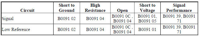
Diagnostic Fault Information
Circuit/System Description
The impact sensors are equipped on vehicles to supplement the supplemental inflatable restraint (SIR) system performance. The impact sensors are electronic and are not part of the deployment loops, but instead provide inputs to the inflatable restraint sensing and diagnostic module. The impact sensors can assist in determining the severity of some frontal and side collisions. The inflatable restraint sensing and diagnostic module uses the input from the impact sensors to assist in determining the severity of a collision further supporting air bag deployment. If the inflatable restraint sensing and diagnostic module determines a deployment is warranted, the inflatable restraint sensing and diagnostic module will cause current to flow through the deployment loops deploying the appropriate air bags. The center front impact sensor and side impact sensors utilize a bidirectional 2-wire circuit. The sensors modulate current on the interface to send identification, state of health, and deployment commands to the inflatable restraint sensing and diagnostic module. The inflatable restraint sensing and diagnostic module serves as a power source and a ground for the sensors. When the ignition is turned ON and input power from the inflatable restraint sensing and diagnostic module is first detected, the sensors respond by performing internal diagnostics and sending an identification to the inflatable restraint sensing and diagnostic module. The inflatable restraint sensing and diagnostic module considers the identification to be valid if the response time is less than 5 seconds. The sensors continually communicate status messages to the inflatable restraint sensing and diagnostic module, which determines if a fault is present in the sensor circuit.
When a fault is detected, the inflatable restraint sensing and diagnostic module may reset the sensors up to 2 times by removing and reapplying power to it. If the fault is still present, the inflatable restraint sensing and diagnostic module will set a DTC.
Conditions for Running the DTC
Ignition voltage is between 9-16 V.
Conditions for Setting the DTC
B0091 01
The inflatable restraint sensing and diagnostic module has detected the center front impact sensor has been shorted to voltage
B0091 02
- The inflatable restraint sensing and diagnostic module has detected the center front impact sensor has been shorted to ground.
- The center front impact sensor current is greater than 23 mA for greater than 5 milliseconds.
B0091 04
- The inflatable restraint sensing and diagnostic module has detected an open/high resistance in the center front impact sensor.
- The inflatable restraint sensing and diagnostic module has not received a message from the center front impact sensor for greater than 375 milliseconds.
B0091 05 and B0091 0C
- The inflatable restraint sensing and diagnostic module has detected the center front impact sensor has been shorted to voltage.
- The inflatable restraint sensing and diagnostic module has detected an open/high resistance in the center front impact sensor.
- The inflatable restraint sensing and diagnostic module has not received a message from the center front impact sensor for greater than 375 milliseconds.
B0091 39
- The inflatable restraint sensing and diagnostic module has received a Not OK (NOK) message from the center front impact sensor.
- The inflatable restraint sensing and diagnostic module has not received a message.
B0091 3A
- The inflatable restraint sensing and diagnostic module has received identification message from the center front impact sensor which does not match the identification stored in the inflatable restraint sensing and diagnostic module memory.
- The inflatable restraint sensing and diagnostic module has reset the center front impact sensor twice without detecting the correct identification message.
B0091 71
The inflatable restraint sensing and diagnostic module has received invalid serial data from the center front impact sensor.
Action Taken When the DTC Sets
- The inflatable restraint sensing and diagnostic module requests the instrument panel cluster to illuminate the AIR BAG indicator.
- The SIR system is disabled and no deployments are allowed.
Conditions for Clearing the DTC
- The condition for setting the DTC no longer exists.
- A history DTC will clear once 100 malfunction-free ignition cycles have occurred.
Reference Information
Schematic Reference
SIR Schematics (Encore), SIR Schematics (Trax)
Connector End View Reference
WIRING SYSTEMS AND POWER MANAGEMENT - COMPONENT CONNECTOR END VIEWS - INDEX - ENCORE WIRING SYSTEMS AND POWER MANAGEMENT - COMPONENT CONNECTOR END VIEWS - INDEX - TRAX
Description and Operation
Supplemental Inflatable Restraint System Description and Operation
Electrical Information Reference
- Circuit Testing
- Testing for Intermittent Conditions and Poor Connections
- Wiring Repairs
- Connector Repairs
Scan Tool Reference
Control Module References for scan tool information
Circuit/System Verification
NOTE:
- Refer to SIR Service Precautions.
- Inspect all terminals for damage or corrosion when disconnecting connectors. Damage or corrosion in the following requires repair or replacement of the affected component/connector.
- Front impact sensor
- Side impact sensor
- Inflatable restraint sensing and diagnostic module
- Front impact sensor wiring harness connector
- Side impact sensor wiring harness connector
- Inflatable restraint sensing and diagnostic module wiring harness connector
- The connector and connector position assurance (CPA) may seat independent of each other. Both the connector and CPA should seat with an audible and/or tactile click. The CPA isolates the shorting-bars within the connector allowing the deployment circuit to operate properly. Replace any CPA that is damaged or missing.
- If the condition is intermittent or cannot be duplicated, disconnect the connectors and add dielectric grease / lubricant (Nyogel 760G or equivalent, meeting GM specification 9986087). This procedure will correct the high resistance condition due to terminal fretting corrosion.
- Verify that DTC B0091 symptom byte 39 or 71 is not set as current.
- If DTC B0091 symptom byte 39 or 71 is set as current
Replace the B63 Side Impact Sensor.
- If DTC B0091 symptom byte 39 or 71 is not set as current
- Verify that DTC B0091 symptom byte 3 A is not set as current.
- If DTC B0091 symptom byte 3 A is set as current
Replace the incorrect B63 Side Impact Sensor
- If DTC B0091 symptom byte 3 A is not set as current
- Verify that DTC B0091 symptom byte 01, 02, 04, or 05 is not set as current.
- If DTC B0091 symptom byte 01, 02, 04, or 05 is set as current
Refer to Circuit/System Testing.
- If DTC B0091 symptom byte 01, 02, 04, 05 is not set as current
- All OK.
Circuit/System Testing
- Ignition OFF. Disconnect the harness connector at the B63 Side Impact Sensor. It may take up to 2 min for all vehicle systems to power down.
- Test for less than 10 ohms between the low reference circuit terminal 2 and ground.
If 10 ohms or greater
Ignition OFF, disconnect the X2 harness connector at the K36 Inflatable Restraint Sensing and Diagnostic Module.
Test for less than 2 ohms in the low reference circuit end to end.
- If 2 ohms or greater, repair the open/high resistance in the circuit
- If less than 2 ohms, replace the K36 Inflatable Restraint Sensing and Diagnostic Module.
- If less than 10 ohms
- Test for greater than 50k ohms between the signal circuit terminal 1 and ground.
If 50k ohms or less
- Disconnect the harness connector at the K36 Inflatable Restraint Sensing and Diagnostic Module.
- Test for infinite resistance between the signal circuit and ground.
- If less than infinite resistance, repair the short to ground on the circuit.
- If infinite resistance, replace the K36 Inflatable Restraint Sensing and Diagnostic Module.
- If greater than 50k ohms
- Ignition ON.
- Test for less than 10 V between the signal circuit terminal 1 and ground.
- If 10 V or greater
- Ignition OFF, disconnect the harness connector at the K36 Inflatable Restraint Sensing and Diagnostic Module.
- Ignition ON, test for less than 1 V between the signal circuit and ground.
- If greater than 1 V, repair the short to voltage on the circuit.
- If less than 1 V, replace the K36 Inflatable Restraint Sensing and Diagnostic Module.
- If less than 10 V
- Ignition OFF, disconnect the X2 harness connector at the K36 Inflatable Restraint Sensing and Diagnostic Module.
- Test for less than 2 ohms between the signal circuit end to end from the B63 Side Impact Sensor terminal 1 and the K36 Inflatable Restraint Sensing and Diagnostic Module terminal 23 X2.
If 2 ohms or greater
Repair the open/high resistance in the circuit.
If less than 2 ohms
- Ignition OFF, reconnect all harness connectors, press in the CPA (if equipped) until an audible and/or tactile click is heard.
- Ignition ON, clear DTCs. Operate the vehicle within the Conditions for Running the DTC.
- Verify the DTC does not set.
- If the DTC sets
Replace the B59 Front Impact Sensor.
- If the DTC does not set
- All OK.
Repair Instructions
Perform the Diagnostic Repair Verification after completing the repair.
- Front End Inflatable Restraint Discriminating Sensor Replacement (Trax), Front End Inflatable Restraint Discriminating Sensor Replacement (Encore)
- Control Module References for inflatable restraint sensing and diagnostic module replacement, programming and setup
