Chevrolet Trax: Door ajar indicator malfunction
Diagnostic Instructions
- Perform the Diagnostic System Check - Vehicle prior to using this diagnostic procedure.
- Review Strategy Based Diagnosis for an overview of the diagnostic approach
- Diagnostic Procedure Instructions provides an overview of each diagnostic category
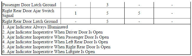
Diagnostic Fault Information
.jpg)
Circuit/System Description
If the vehicle is equipped with power windows without the express features or with manual crank windows, the body control module (BCM) will provide a 12 V signal to each door ajar switch via the door ajar switch signal circuit. The door ajar switches are normally open when the door is fully closed. When a door is opened, the door ajar switch contacts close providing a path to ground. The instrument cluster receives a serial data message from the BCM indicating the door ajar status, the instrument cluster will then display the door ajar icon.
If the vehicle is equipped with express power windows, the window motors or the window switches each provide a 12 V signal to their respective door ajar switch signal circuits. The door ajar switches are integral to each door latch assembly. When a door is opened, the normally open door ajar switch closes. With the door ajar switch closed, ground is provided to the door ajar switch signal circuit and the voltage within the signal circuit drops. The window motor or the window switch will detect the voltage drop and will send a serial data message to the body control module which will then send a message to the instrument cluster to command the door ajar icon.
Reference Information
Schematic Reference
Door Lock/Indicator Schematics (Encore), Door Lock/Indicator Schematics (Trax)
Connector End View Reference
WIRING SYSTEMS AND POWER MANAGEMENT - COMPONENT CONNECTOR END VIEWS - INDEX - ENCORE WIRING SYSTEMS AND POWER MANAGEMENT - COMPONENT CONNECTOR END VIEWS - INDEX - TRAX
Description and Operation
Door Ajar Indicator Description and Operation
Electrical Information Reference
- Circuit Testing
- Connector Repairs
- Testing for Intermittent Conditions and Poor Connections
- Wiring Repairs
Scan Tool Reference
Control Module References for scan tool information
Circuit/System Verification
- Ignition ON.
- Verify the appropriate scan tool Door Ajar Switch parameter changes between Inactive and Active when opening and closing the driver door, the passenger door, the left rear door and right rear door.
- If any parameter does not change
Refer to Circuit/System Testing - Door Ajar Malfunction.
- If all the parameters change
- Verify the scan tool Rear Closure Ajar Switch parameter changes between Inactive and Active when opening and closing the liftgate.
- If the parameter does not change
Refer to Circuit/System Testing - Liftgate Ajar Malfunction.
- If the parameter changes
- All OK.
Circuit/System Testing
Door Ajar Malfunction
- Ignition OFF and all vehicle systems OFF, disconnect the harness connector at the appropriate A23 Door Latch Assembly. It may take up to 2 minutes for all vehicle systems to power down.
- Test for less than 10 ohms between the ground circuit terminal listed below and ground.
- A23D Door Latch Assembly-Driver - ground circuit terminal 8
- A23P Door Latch Assembly-Passenger - ground circuit terminal 3
- A23LR Door Latch Assembly-Left Rear - ground circuit terminal 8
- A23RR Door Latch Assembly-Right Rear - ground circuit terminal 3
- If 10 ohms or greater
- Ignition OFF.
- Test for less than 2 ohms in the ground circuit end to end.
- If 2 ohms or greater, repair the open/high resistance in the circuit.
- If less than 2 ohms, repair the open/high resistance in the ground connection.
- If less than 10 ohms
- Ignition ON.
- Verify the appropriate scan tool Door Ajar Switch parameter is Inactive.
- If not Inactive
- Ignition OFF, disconnect the harness connector at the appropriate component listed below:
- M74D Window Motor-Driver (AXG)
- S79D Window Switch-Driver (AEC)
- M74P Window Motor-Passenger (AEF)
- S79P Window Switch-Passenger (AED)
- M74LR Window Motor-Left Rear (AER)
- S79LR Window Switch-Left Rear (AEQ)
- M74RR Window Motor-Right Rear (AER)
- S79RR Window Switch-Right Rear (AEQ)
- K9 Body Control Module (A55, A66, A33 or crank windows)
- Test for infinite resistance between the signal circuit terminal listed below and ground.
- A23D Door Latch Assembly-Driver - signal circuit terminal 6
- A23P Door Latch Assembly-Passenger - signal circuit terminal 1
- A23LR Door Latch Assembly-Left Rear - signal circuit terminal 6
- A23RR Door Latch Assembly-Right Rear - signal circuit terminal 1
- If less than infinite resistance, repair the short to ground on the circuit.
- If infinite resistance, replace the appropriate component.
- If Inactive
- Install a 3 A fused jumper wire between the signal circuit terminal listed below and ground.
- A23D Door Latch Assembly-Driver - signal circuit terminal 6
- A23P Door Latch Assembly-Passenger - signal circuit terminal 1
- A23LR Door Latch Assembly-Left Rear - signal circuit terminal 6
- A23RR Door Latch Assembly-Right Rear - signal circuit terminal 1
- Verify the scan tool Door Ajar Switch parameter is Active.
- If not Active
- Ignition OFF, remove the fused jumper wire, disconnect the harness connector at the appropriate component listed below, ignition ON.
- M74D Window Motor-Driver (AXG)
- S79D Window Switch-Driver (AEC)
- M74P Window Motor-Passenger (AEF)
- S79P Window Switch-Passenger (AED)
- M74LR Window Motor-Left Rear (AER)
- S79LR Window Switch-Left Rear (AEQ)
- M74RR Window Motor-Right Rear (AER)
- S79RR Window Switch-Right Rear (AEQ)
- K9 Body Control Module (A55, A66, A33 or crank windows)
- Test for less than 1 V between the signal circuit and ground.
- If 1 V or greater, repair the short to voltage on the circuit.
- If less than 1 V
- Test for less than 2 ohms in the signal circuit end to end.
- If 2 ohms or greater, repair the open/high resistance in the circuit.
- If less than 2 ohms, replace the appropriate component.
- If Active
- Test or replace the A23 Door Latch Assembly.
Liftgate Ajar Switch
- Ignition OFF and all vehicle systems OFF, disconnect the harness connector at the M30 Liftgate Latch. It may take up to 2 minutes for all vehicle systems to power down.
- Test for less than 10 ohms between the ground circuit terminal 1 and ground.
If not Inactive
- Ignition OFF, disconnect the harness connector at the K9 Body Control Module.
- Test for infinite resistance between the signal circuit terminal 2 and ground.
- If less than infinite resistance, repair the short to ground on the circuit.
- If infinite resistance, replace the K9 Body Control Module.
- If Inactive
- Install a 3 A fused jumper wire between the signal circuit terminal 2 and ground circuit terminal 1.
- Verify the scan tool Rear Closure Ajar Switch parameter is Active.
- If not Active
- Ignition OFF, remove the fused jumper wire, disconnect the harness connector at the K9 Body Control Module, ignition ON.
- Test for less than 1 V between the signal circuit and ground.
- If 1 V or greater, repair the short to voltage on the circuit.
- If less than 1 V
- Test for less than 2 ohms in the signal circuit end to end.
- If 2 ohms or greater, repair the open/high resistance in the circuit.
- If less than 2 ohms, replace the K9 Body Control Module.
- If Active
- Test or replace the M30 Liftgate Latch.
Component Testing
- Ignition OFF, disconnect the harness connector at the appropriate A23 Door Latch Assembly.
- Test for infinite resistance between the terminals listed below with the switch in the open position.
- A23D Door Latch Assembly-Driver - signal terminal 6 and ground terminal 8
- A23P Door Latch Assembly-Passenger - signal terminal 1 and ground terminal 3
- \A23LR Door Latch Assembly-Left Rear - signal terminal 6 and ground terminal 8
- A23RR Door Latch Assembly-Right Rear - signal terminal 1 and ground terminal 3
- If less than infinite resistance
Replace the A23 Door Latch Assembly.
- If infinite resistance
- Test for less than 3 ohms between the terminals listed below with the switch in the closed position.
- A23D Door Latch Assembly-Driver - signal terminal 6 and ground terminal 8
- A23P Door Latch Assembly-Passenger - signal terminal 1 and ground terminal 3
- A23LR Door Latch Assembly-Left Rear - signal terminal 6 and ground terminal 8
- A23RR Door Latch Assembly-Right Rear - signal terminal 1 and ground terminal 3
- If 3 ohms or greater
Replace the A23 Door Latch Assembly.
- If less than 3 ohms
- All OK
Repair Instructions
Perform the Diagnostic Repair Verification after completing the repair.
- Front Side Door Latch Replacement
- Rear Side Door Latch Replacement
- Front Side Door Window Switch Replacement (Driver Side, Encore) , Front Side Door Window Switch Replacement (Passenger Side, Encore) , Front Side Door Window Switch Replacement (Driver Side, Trax) , Front Side Door Window Switch Replacement (Passenger Side, Trax)
- Rear Side Door Window Switch Replacement
- Front Side Door Window Regulator Motor Replacement
- Rear Side Door Window Regulator Motor Replacement
- Liftgate Latch Replacement
- Control Module References for body control module replacement, programming and setup
