Chevrolet Trax: Cylinder head cleaning and inspection
Special Tools
- EN-6216 Gauge
- EN-6216-200/300/400 Gauge Instruments
For equivalent regional tools refer to Special Tools.
Cleaning Procedure
- Remove any old thread sealant, gasket material or sealant.
- Clean all cylinder head surfaces with non-corrosive sealant.
WARNING: Refer to Safety Glasses Warning .
- Blow out all the oil galleries using compressed air.
- Remove any carbon deposits from the combustion chamber.
Visual Inspection
- Inspect the cylinder head camshaft bearing surfaces for the following conditions:
- Excessive scoring or pitting
- Discoloration from overheating
- Deformation from excessive wear
- If the camshaft bearing journals appear to be scored or damaged, you must replace the cylinder head. DO NOT machine the camshaft bearing journals.
- If any of the above conditions exist on the camshaft bearing surfaces, replace the cylinder head.
- Inspect the cylinder head for the following:
- Cracks, damage or pitting in the combustion chambers.
- Debris in the oil galleries - Continue to clean the galleries until all debris is removed.
- Coolant leaks or damage to the deck face sealing surface - If coolant leaks are present, measure the surface war page as described under cylinder head measurement - deck flatness inspection.
- Damage to any gasket surfaces.
- Burnt or eroded areas in the combustion chamber.
- Cracks in the exhaust ports and combustion chambers.
- External cracks in the water passages.
- Restrictions in the intake or exhaust passages.
- Restrictions in the cooling system passages.
- Rusted, damaged or leaking core plugs.
- If the cylinder head is cracked or damaged, it must be replaced. No welding or patching of the cylinder head is allowed.
Valve Inspection And Measurement
.gif)
Fig. 323: Valve Inspection And Measurement
- Clean the valves of carbon and oil. Carbon can be removed with a wire brush.
- Inspect the valves for the following conditions:
- Inspect the valve faces for burning and cracking (1). If pieces are broken, replace the valve and inspect the corresponding piston and cylinder head area for damage.
- Inspect the valve for straightness and distortion (2). Distorted valve must be replaced.
- Inspect the valve stem for wear (3).
- Inspect the valve key grooves for chipping and wear (5). Replace the valve if chipped or worn.
.gif)
Fig. 324: Measuring Valve Length Using Slide Gauge
- Measure the valve length (2). Use a slide gauge (1). Refer to Engine Mechanical Specifications to find the permitted values.
.gif)
Fig. 325: Measuring Valve Stem Diameter Using Micrometer Gauge
- Measure the valve stem diameter. Use a micrometer gauge (2). Refer to Engine Mechanical Specifications to find the permitted values. Note the measurement results.
Cylinder Head Measurement
.gif)
Fig. 326: Using Straightedge To Inspect Cylinder Head Sealing Surface For
Flatness
- Inspect the cylinder head sealing surface for flatness. Use a straightedge (1). Refer to Engine Mechanical Specifications to find the permitted values. If the measurement does not show the permitted values, replace the cylinder head. Machining is NOT allowed.
.gif)
Fig. 327: Checking Valve Stem To Guide Clearance Measurement
- Prepare the gauge for valve stem to guide clearance measurement. Assemble the EN-6216 gauge and the EN-6216-200/300/400 gauge instruments as followed:
- Install the extension (5) to the support (4).
- Install the inside caliper (2) to the extension (5).
- Install the gauge (3) to the support (4) and pretension to 1 mm (0.0394 in).
- Install the calibration washer (1) as shown to justify the gauge.
- Adjust the gauge to 0 mm (0 in) by rotating the instrument dial.
- Cautious remove the calibration washer (1).
.gif)
Fig. 328: Measuring Valve Guide Inner Diameter
- Measure the valve guide inner diameter (2) as shown in different areas (3). Use EN-6216 gauge (1) and gauge instruments. Note the measurement results. Refer to Engine Mechanical Specifications to find the permitted values.
- Substract the valve stem diameter from valve guide inner diameter to calculate the valve stem to guide clearance. Refer to Engine Mechanical Specifications to find the permitted values.
- Turn the cylinder head upside down.
CYLINDER HEAD ASSEMBLE
Special Tools
- EN-958 Valve Stem Seal Installer
- EN-8062 Valve Spring Compressor
- EN-8062-5 Adapter
- EN-50717-2 Compressor Assembly of EN-50717 Kit
For equivalent regional tools, refer to Special Tools.
.gif)
Fig. 329: Valve Stem Oil Seal And Installer
- Lubricate the valve stem and the valve guide with clean engine oil.
NOTE: Ensure all valve train components will be installed in their original position.
- Install the valve (5).
- Install the NEW valve stem oil seal (4), using the EN-958 installer (2).
- Loosely install the valve spring (3) and the valve spring retainer (1).
.gif)
Fig. 330: Valve Spring Compressor And Adapter Assembly
- Install the EN-50717-2 assembly (1) to the EN-8062 compressor (4).
- Install the EN-8062-5 adapter (3) to the EN-8062 compressor.
- Install the compressor assembly to the cylinder head, so that the
adapter (5) of the EN-50717-2 assembly
(1) contacts the valve spring retainer properly and the EN-8062-5 adapter
(3) contacts the valve disc (2).
Prefix the EN-8062 compressor (4).
.gif)
Fig. 331: Valve Spring Retainer And Valve Spring
CAUTION: The valve stem keys must correctly seat in the valve spring cap.
Engine damage may occur by not installing properly.
- Apply pressure to the EN-50717-2 assembly to push down the vale spring retainer (1) and compress the valve spring (3) until the valve keys (2) can be inserted. Carefully insert the valve keys then, so that they are proper installed to the valve stem grooves.
- Carefully release the tension from the EN-50717-2 assembly.
- Inspect the valve keys and valve spring retainers for proper seat.
- Remove the compressor assembly from the cylinder head.
- Repeat the procedure with the remaining valves.
ENGINE BLOCK DISASSEMBLE
.gif)
Fig. 332: Knock Sensor, Bolt, Cylinder Head Guide Sleeves And Transmission
Guide Sleeves
- Remove the knock sensor bolt (3).
- Remove the knock sensor (2).
- Remove the 2 cylinder head guide sleeves (1). Use suitable pliers.
- Remove the 2 transmission guide sleeves (4) and (5). Use suitable pliers.
.gif)
Fig. 333: Piston Oil Nozzles And Bolts
- Remove the 4 piston oil nozzle bolts (2).
- Remove the 4 piston oil nozzles (1).
ENGINE BLOCK ASSEMBLE
.gif)
Fig. 334: Piston Oil Nozzles And Bolts
- Install the 4 piston oil nozzles (1).
CAUTION: Refer to Fastener Caution .
- Install the 4 piston oil nozzle bolts (2) and tighten to 25 N.m (18 lb ft).
.gif)
Fig. 335: Knock Sensor, Bolt, Cylinder Head Guide Sleeves And Transmission
Guide Sleeves
- Install the knock sensor (2).
- Install the knock sensor bolt (3) and tighten to 20 N.m (15 lb ft).
- Install the 2 cylinder head guide sleeves (1). Use a rubber mallet.
- Install the 2 transmission guide sleeves (4) and (5). Use a rubber mallet.
PISTON AND CONNECTING ROD DISASSEMBLE
Special Tool
EN-49941 Remover / Installer Piston Retainer Ring
For equivalent regional tools, refer to Special Tools.
.gif)
Fig. 336: Using Piston Ring Pliers
WARNING: Handle the piston carefully. Worn piston rings are sharp and may cause bodily injury.
- Remove the piston rings. Use piston ring pliers (1)
.gif)
Fig. 337: Upper Compression Ring, Lower Compression Ring, Oil Rings And Oil
Ring Spacer
- The piston rings are ordered as followed:
- Upper compression ring (1)
- Lower compression ring (2)
- Oil rings and oil ring spacer (3) and (4)
- Install the piston and connecting rod assembly to a bench vise. Use aluminium braces
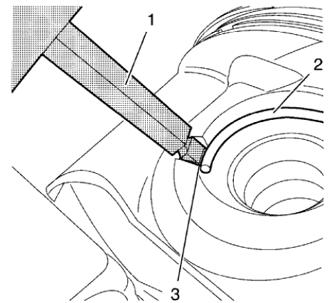
Fig. 338: Piston Pin Retainer, Remover And Notch
WARNING: Use extreme care when removing snap rings. Always wear adequate eye protection in order to avoid personal injury.
- Apply the EN-49941 remover (1) in the notch (3) to the piston pin retainer (2) and remove it.
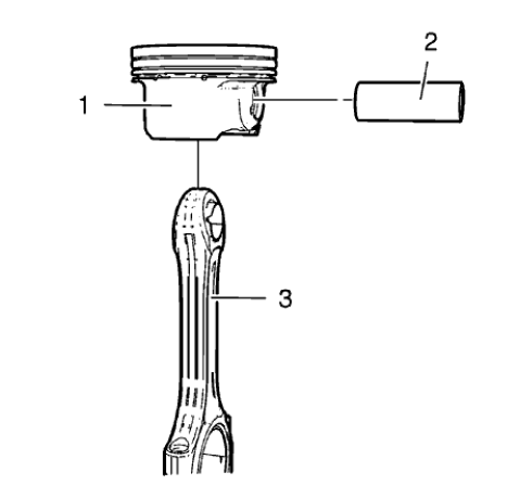
Fig. 339: Connecting Rod, Piston And Piston Pin
- Remove the piston pin (2) and the connecting rod (3) from the piston (1).
PISTON, CONNECTING ROD, AND BEARING CLEANING AND INSPECTION
Special Tools
EN-470-B Angular Torque Wrench
For equivalent regional tools, refer to Special Tools.
Visual Inspection And Cleaning Procedure
Connecting Rod
WARNING: Wear safety glasses when using compressed air in order to prevent eye injury.
- Clean the connecting rods in solvent and dry with compressed air.
- Inspect the connecting rod for the following:
- Signs of being twisted, bent, nicked or cracked
- Scratches or abrasion on the connecting rod bearing seating surfaces
Piston
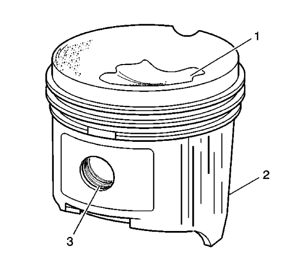
Fig. 340: Identifying Piston Damage Inspection Areas
- Clean the piston with a cleaning solvent. DO NOT wire brush any parts of the piston.
- Clean the piston ring grooves.
- Inspect the piston on the following:
- Cracked ring lands, skirts or pin bosses
- Ring grooves for nicks
- Eroded areas on the top of the piston (1)
- Scuffed or damaged skirts (2)
- Worn piston pin bores (3)
- If there is any excessive wear, replace the piston.
- Measure the clearance between piston pin and piston bore.
Piston And Connecting Rod Measurement Procedure
Piston Ring Clearance
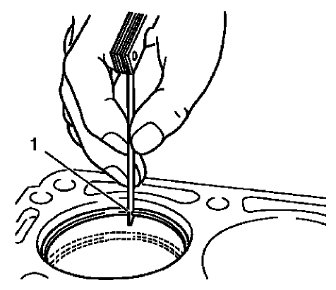
Fig. 341: Measuring Piston Ring End Clearance
- Install the piston rings to the cylinder as shown (1) and measure the piston ring end gap. Compare the measurements with those provided below:
- The upper compression ring end gap should be 0.4-0.6 mm (0.0157-0.0236 in).
- The lower compression ring end gap should be 0.4-0.6 mm (0.0157-0.0236 in).
- The oil ring end gap should be 0.2-0.9 mm (0.0079-0.0354 in).
- If the clearance is greater than the provided specifications, the piston rings must be replaced.
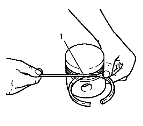
Fig. 342: Measuring Piston Ring Side Clearance
- Measure the piston ring side clearance as shown (1). Compare the measurements with those provided below:
- The upper compression ring side clearance should be 0.025-0.07 mm (0.001-0.0028 in).
- The lower compression ring side clearance should be 0.025-0.07 mm (0.001-0.0028 in).
- The oil ring side clearance should be 0.04-0.12 mm (0.0016-0.0047 in).
- If the clearance is greater than the provided specifications, replace the piston rings.
- If the clearance is still to great, replace the pistons.
Connecting Rod Bearing Clearance (With Micrometer Gauge Internal Measuring Device)
- Install the connecting bearings and the connecting rod bearing caps.
- Tighten the connecting rod bearing cap bolts in the following sequence:
CAUTION: Refer to Fastener Caution
NOTE: The old bolts can be reused for the measuring procedure.
- Tighten the connecting rod bearing cap bolts to 10 N.m (89 lb in).
- Tighten the bolts to an additional 60 degrees using EN-470-B wrench.
- Tighten the bolts to an additional 15 degrees using EN-470-B wrench.
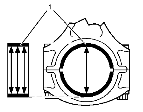
Fig. 343: Measuring Connecting Rod Bearing Diameters
- Measure the connecting rod bearing diameters at 3 points as shown (1). Use a internal measuring device.
- Calculate the average connecting rod inner diameter.
Formula: 1. result + 2. result + 3. result / 3
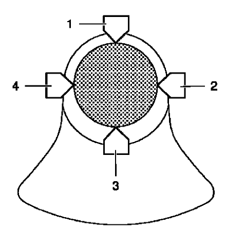
Fig. 344: Connecting Rod Journal Diameter Points
- Measure the connecting rod journal diameter at 2 points between (1) and (3) and between (2) and (4). Use a micrometer gauge.
- Calculate the average connecting rod journal diameter.
Formula: 1. result + 2. result / 2.
- Substract the average connecting rod journal diameter from the average connecting rod bearing diameter in order to determine the connecting rod bearing clearance.
The clearance should be 0.013-0.061 mm (0.0005-0.0024 in).
