Chevrolet Trax: Camshaft actuator system description
Camshaft Actuator System Overview
.gif)
Fig. 1: Identifying Camshaft Actuator System Components
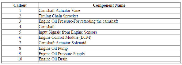
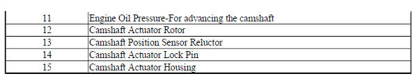
The camshaft actuator system enables the engine control module (ECM) to change camshaft timing of all 4 camshafts while the engine is operating. The camshaft position (CMP) actuator assembly (15) varies the camshaft position in response to directional changes in oil pressure. The CMP actuator solenoid valve controls the oil pressure that is applied to advance or retard a camshaft. Modifying camshaft timing under changing engine demand provides better balance between the following performance concerns:
- Engine power output
- Fuel economy
- Tailpipe emissions
The CMP actuator solenoid valve (7) is controlled by the ECM. The crankshaft position (CKP) sensor and the CMP sensors are used to monitor changes in camshaft positions. The ECM uses the following information in order to calculate the desired camshaft positions:
- Engine coolant temperature
- Calculated engine oil temperature (EOT)
- Mass air flow (MAF)
- Throttle position (TP)
- Vehicle speed
- Volumetric efficiency
Operation
The CMP actuator assembly has an outer housing that is driven by an engine timing chain. Inside the assembly is a rotor with fixed vanes that is attached to the camshaft. Oil pressure that is applied to the fixed vanes will rotate a specific camshaft in relationship to the crankshaft. The movement of the intake camshafts will advance the intake valve timing. The movement of the exhaust camshafts will retard the exhaust valve timing. When oil pressure is applied to the return side of the vanes, the camshafts will return to 0 crankshaft degrees, or top dead center (TDC). The CMP actuator solenoid valve directs the oil flow that controls the camshaft movement. The ECM commands the CMP solenoid to move the solenoid plunger and spool valve until oil flows from the advance passage (11). Oil flowing thru the CMP actuator assembly from the CMP solenoid advance passage applies pressure to the advance side of the vanes in the CMP actuator assembly. When the camshaft position is retarded, the CMP actuator solenoid valve directs oil to flow into the CMP actuator assembly from the retard passage (3). The ECM can also command the CMP actuator solenoid valve to stop oil flow from both passages in order to hold the current camshaft position.
The ECM operates the CMP actuator solenoid valve by pulse width modulation (PWM) of the solenoid coil.
The higher the PWM duty cycle, the larger the change in camshaft timing. The CMP actuator assembly also contains a lock pin (14) that prevents movement between the outer housing and the rotor vane assembly. The lock pin is released by oil pressure before any movement in the CMP actuator assembly takes place. The ECM is continuously comparing CMP sensor inputs with CKP sensor input in order to monitor camshaft position and detect any system malfunctions. If a condition exists in either the intake or exhaust camshaft actuator system, the opposite bank, intake or exhaust, camshaft actuator will default to 0 crankshaft degrees.
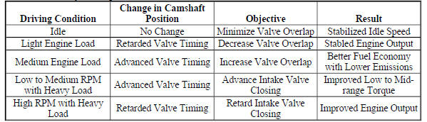
CMP Actuator System Operation
ELECTRONIC IGNITION SYSTEM DESCRIPTION
Electronic Ignition System Operation
The electronic ignition system produces and controls the high energy secondary spark. This spark ignites the compressed air/fuel mixture at precisely the correct time, providing optimal performance, fuel economy, and control of exhaust emissions. The engine control module (ECM) collects information from the crankshaft position sensor and the intake/exhaust camshaft position sensors to determine the sequence, dwell, and timing of the spark for each cylinder. The ECM transmits a frequency signal to the ignition coil module on the individual ignition control circuits to fire the spark plugs.
Crankshaft Position Sensor
The crankshaft position sensor is an externally magnetically biased digital output integrated circuit sensing device. The sensor provides a pulse for each magnetic pole of the encoder wheel on the crankshaft. The sensor produces an ON/OFF DC voltage of varying frequency, with 58 output pulses per crankshaft revolution. The frequency of the sensor output depends on the velocity of the crankshaft. The ECM uses sensor signal pulse to determine crankshaft speed and position to calculate the best timing for ignition and fuel injection. The ECM also uses the crankshaft position sensor information to control camshaft phasing and to detect cylinder misfire.
The ECM also has a dedicated replicated crankshaft position sensor signal output circuit that may be used as an input signal to other modules for monitoring engine RPM.
The crankshaft position sensor is connected to the engine control module by the circuits listed below:
- A 5 V reference circuit
- A low reference circuit
- A signal circuit
Crankshaft Encoder Wheel
The crankshaft encoder wheel is part of the crankshaft. The encoder wheel consists of 58 tooth and a reference gap. Each tooth on the encoder wheel is spaced 6º apart with a 12º space for the reference gap. The pulse from the reference gap is known as the sync pulse. The sync pulse is used to synchronize the ignition coil module firing sequence with the crankshaft position while the other tooth provides cylinder location during a revolution.
Camshaft Position Sensors
The intake and exhaust camshaft position sensors are each triggered by a notched reluctor wheel built onto the camshaft sprockets. The four signal pulses occur every camshaft revolution. Each notch is a different size which is used to identify the compression stroke of each cylinder and to enable sequential fuel injection. The camshaft position sensors are connected to the ECM by the circuits listed below:
- A 5 V reference circuit
- A low reference circuit
- A signal circuit
Knock Sensor
The knock sensor system enables the control module to control the ignition timing for the best possible performance while protecting the engine from potentially damaging levels of detonation, also known as spark knock. The knock sensor system uses 1 or 2 flat response 2-wire sensors. The sensor uses piezo-electric crystal technology that produces an AC voltage signal of varying amplitude and frequency based on the engine vibration or noise level. The amplitude and frequency depend upon the level of knock that the knock sensor detects. The control module receives the knock sensor signal through the signal circuit. The knock sensor ground is supplied by the control module through the low reference circuit.
The control module learns a minimum noise level, or background noise, at idle from the knock sensor and uses calibrated values for the rest of the RPM range. The control module uses the minimum noise level to calculate a noise channel. A normal knock sensor signal will ride within the noise channel. As engine speed and load change, the noise channel upper and lower parameters will change to accommodate the normal knock sensor signal, keeping the signal within the channel. In order to determine which cylinders are knocking, the control module only uses knock sensor signal information when each cylinder is near top dead center (TDC) of the firing stroke. If knock is present, the signal will range outside of the noise channel.
If the control module has determined that knock is present, it will retard the ignition timing to attempt to eliminate the knock. The control module will always try to work back to a zero compensation level, or no spark retard. An abnormal knock sensor signal will stay outside of the noise channel or will not be present. Knock sensor diagnostics are calibrated to detect faults with the knock sensor circuitry inside the control module, the knock sensor wiring, or the knock sensor voltage output. Some diagnostics are also calibrated to detect constant noise from an outside influence such as a loose/damaged component or excessive engine mechanical noise.
Ignition Coil Module
The ignition coil module integrates the 4 coils and the ignition control module within a single sealed component.
The ignition coil module has the following circuits:
- An ignition voltage circuit
- A ground
- A low reference circuit
- 4 ignition coil control circuits
The ECM controls the individual coils by transmitting timing pulses on the ignition coil control circuit to each ignition coil to enable a spark event.
The spark plugs are connected to each coil by a short boot. The boot contains a spring that conducts the spark energy from the coil to the spark plug. The spark plug electrode is coated with platinum for long wear and higher efficiency.
Engine Control Module [ECM]
The ECM controls all ignition system functions and constantly adjusts the spark timing. The ECM monitors information from various sensor inputs that include the following:
- The crankshaft position sensor
- The accelerator pedal position (APP)
- The manifold absolute pressure (MAP) sensor
- The intake air temperature (IAT) sensor
- The vehicle speed sensor (VSS)
- The engine knock sensor
- The engine coolant temperature (ECT) sensor
- The mass airflow (MAF) sensor
- The camshaft position sensors
