Chevrolet Trax: Brake warning indicator malfunction (WITH J41)
Diagnostic Instructions
- Perform the Diagnostic System Check - Vehicle prior to using this diagnostic procedure.
- Review Strategy Based Diagnosis for an overview of the diagnostic approach.
- Diagnostic Procedure Instructions provides an overview of each diagnostic category
Diagnostic Fault Information
.jpg)
Circuit/System Description
The instrument cluster turns ON the brake warning indicator for 5 s after ignition ON. The body control module monitors the parking brake switch and the brake fluid level switch and will request the instrument cluster via serial data to turn the brake warning indicator ON when the parking brake is applied or low brake fluid is detected.
Reference Information
Schematic Reference
Hydraulic Brake Schematics (Encore), Hydraulic Brake Schematics (Trax)
Connector End View Reference
WIRING SYSTEMS AND POWER MANAGEMENT - COMPONENT CONNECTOR END VIEWS - INDEX - ENCORE WIRING SYSTEMS AND POWER MANAGEMENT - COMPONENT CONNECTOR END VIEWS - INDEX - TRAX
Description and Operation
Hydraulic Brake System Description and Operation
Electrical Information Reference
- Circuit Testing
- Connector Repairs
- Testing for Intermittent Conditions and Poor Connections
- Wiring Repairs
Scan Tool Reference
Control Module References for scan tool information
Circuit/System Verification
- Verify that the brake fluid is above minimum level.
If low
Refer to Brake Fluid Loss.
If above minimum level
- Ignition ON.
- Verify the scan tool Brake Fluid Level Sensor is OK.
- If the parameter is Low
Refer to Circuit/System Testing - Brake Fluid Level Switch Malfunction.
- If the parameter is OK
- Verify the scan tool Park Brake Switch parameter changes between Applied and Released while applying and releasing the parking brake.
- If the parameter does not change
Refer to Circuit/System Testing - Park Brake Switch Malfunction.
- If the parameter changes
- Verify the brake warning indicator turns ON and OFF, when commanding the instrument cluster All Indicators On and Off with a scan tool.
- If the brake warning indicator does not turn ON and OFF
Replace the P16 Instrument Cluster.
- If the brake warning indicator turns ON and OFF
- All OK.
Circuit/System Testing
NOTE: Circuit/System Verification must be performed before Circuit/System Testing.
Brake Fluid Level Sensor Malfunction
- Ignition OFF and all vehicle systems OFF, disconnect the harness connector at the B20 Brake Fluid Level Switch. It may take up to 2 min for all vehicle systems to power down.
- Test for less than 10 ohms between the ground circuit terminal 2 and ground.
If 10 ohms or greater
- Ignition OFF.
- Test for less than 2 ohms in the ground circuit end to end.
- If 2 ohms or greater, repair the open/high resistance in the circuit.
- If less than 2 ohms, repair the open/high resistance in the ground connection.
If less than 10 ohms
- Ignition ON.
- Verify the scan tool Brake Fluid Level Sensor parameter is Low.
If the parameter is not Low
- Ignition OFF, disconnect the harness connector at the K9 Body Control Module.
- Test for infinite resistance between the signal circuit terminal 1 and ground.
- If less than infinite resistance, repair the short to ground on the circuit.
- If infinite resistance, replace the K9 Body Control Module.
If the parameter is Low
- Install a 3 A fused jumper wire between the signal circuit terminal 1 and ground.
- Verify the scan tool Brake Fluid Level Sensor parameter is OK.
If the parameter is Low
- Ignition OFF, disconnect the harness connector at the K9 Body Control Module, ignition ON.
- Test for less than 1 V between the signal circuit and ground.
- If 1 V or greater, repair the short to voltage on the circuit.
- If less than 1 V.
- Test for less than 2 ohms in the signal circuit end to end.
- If 2 ohms or greater, repair the open/high resistance in the circuit.
- If less than 2 ohms, replace the K9 Body Control Module
If the parameter is OK
- Test or replace the B20 Brake Fluid Level Switch.
Park Brake Switch Malfunction
- Ignition OFF, disconnect the harness connector at the B80 Park Brake Switch.
- Verify that the B80 Park Brake Switch has no physical damage or incorrect installation.
If physical damage or incorrect installation is found
Test or replace the B80 Park Brake Switch.
If the inspection is OK
- Ignition ON.
- Verify the scan tool Park Brake Switch parameter is Released.
If the parameter is Applied
- Ignition OFF, disconnect the harness connector at the K9 Body Control Module.
- Test for infinite resistance between the signal circuit terminal A and ground.
- If less than infinite resistance, repair the short to ground on the circuit.
- If infinite resistance, replace the K9 Body Control Module.
If the parameter is Released
- Install a 3 A fused jumper wire between the signal circuit terminal A and ground.
- Verify the scan tool Park Brake Switch parameter is Applied.
If the parameter is Released
- Ignition OFF, disconnect the harness connector at the K9 Body Control Module, ignition ON.
- Test for less than 1 V between the signal circuit and ground
- If 1 V or greater, repair the short to voltage on the circuit.
- If less than 1 V.
- Test for less than 2 ohms in the signal circuit end to end.
- If 2 ohms or greater, repair the open/high resistance in the circuit.
- If less than 2 ohms, replace theK9 Body Control Module.
If the parameter is Applied
- Test or replace the B80 Park Brake Switch.
Repair Instructions
Perform the Diagnostic Repair Verification after completing the repair.
- Brake Fluid Level Indicator Switch Replacement
- Parking Brake Indicator Switch Replacement
- Control Module References for body control module replacement, programming and setup.
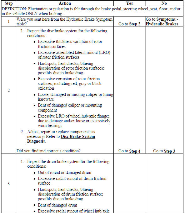
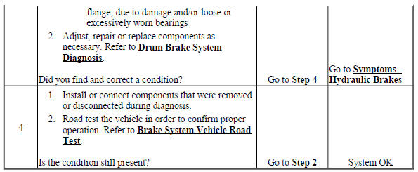
Brake pulsation
Brake Pulsation
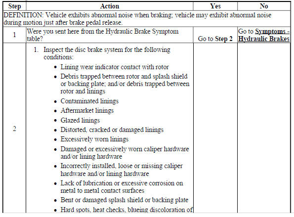
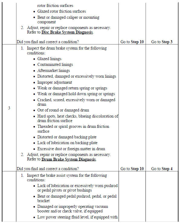
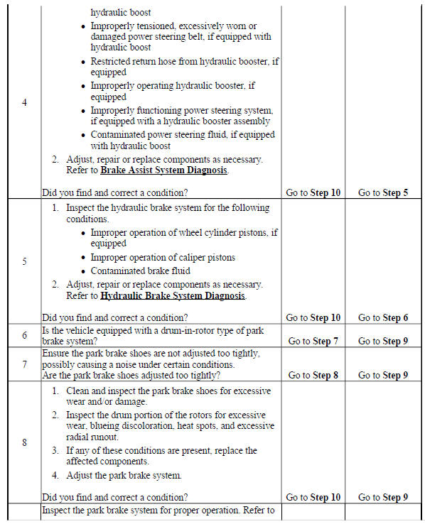
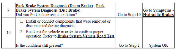
BRAKE SYSTEM NOISE
Brake System Noise