Chevrolet Trax: Scan tool does not communicate with low speed gmlan device
Diagnostic Instructions
- Perform the Diagnostic System Check - Vehicle prior to using this diagnostic procedure.
- Review Strategy Based Diagnosis for an overview of the diagnostic approach.
- Diagnostic Procedure Instructions provides an overview of each diagnostic category.
Diagnostic Fault Information
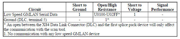
Circuit/System Description
The serial data is transmitted over a single wire to the appropriate devices. The transmission speed for GMLAN low speed is up to 83.33 kbit/s. Under normal vehicle operating conditions, the speed of the bus is 33.33 kbit/s.
The devices toggle the serial data circuit between 0-5 V during normal communications. To wake the devices connected to the low speed GMLAN serial data circuit, a voltage wake up pulse of 10 V is sent out. If serial data is lost, devices will set a no communication code against the non-communicating device. A loss of serial data communications DTC does not represent a failure of the device that set it.
Diagnostic Aids
Sometimes, while diagnosing a specific customer concern or after a repair, you may notice a history U code present. However, there is no associated "current" or "active" status. Loss of communication U codes such as these can set for a variety of reasons. Many times, they are transparent to the vehicle operator and technician, and/or have no associated symptoms. Eventually, they will erase themselves automatically after a number of fault-free ignition cycles. This condition would most likely be attributed to one of these scenarios:
- A device on the data communication circuit was disconnected while the communication circuit is awake.
- Power to one or more devices was interrupted during diagnosis
- A low battery condition was present, so some devices stop communicating when battery voltage drops below a certain threshold.
- Battery power was restored to the vehicle and devices on the communication circuit did not all re- initialize at the same time.
- If a loss of communication U- code appears in history for no apparent reason, it is most likely associated with one of the scenarios above. These are all temporary conditions and should never be interpreted as an intermittent fault, causing you to replace a part.
Do not replace a device reporting a U code. The U code identifies which device needs to be diagnosed for a communication issue.
Communication may be available between the device and the scan tool with the low speed GMLAN serial data system inoperative. This condition is due to the device using both the high and low speed GMLAN systems.
An open in the low speed GMLAN serial data circuit between the splice pack and a device will only affect that specific device. This type of failure will set a loss of communication DTC for each device affected, and the other devices will still communicate.
An open in the X84 Data Link Connector (DLC) ground circuit terminal 5 will allow the scan tool to operate but not communicate with the vehicle.
The engine may not start when there is a total malfunction of the low speed GMLAN serial data circuit.
Technicians may find various Local Area Network (LAN) communication Diagnostic Trouble Codes (DTC) and no low speed LAN communications with the scan tool.
These conditions may be caused by the installation of an aftermarket navigation radio device (see bulletins). Some customers may comment of one or more of the following concerns:
- Vehicle will not crank
- Vehicle cranks but will not start
- Vehicle stability enhancement system warning lights and messages
- PRNDL gear indicator position errors
Reference Information
Schematic Reference
- Data Communication Schematics (Encore), Data Communication Schematics (Trax)
- Control Module References
Connector End View Reference
WIRING SYSTEMS AND POWER MANAGEMENT - COMPONENT CONNECTOR END VIEWS - INDEX - ENCORE WIRING SYSTEMS AND POWER MANAGEMENT - COMPONENT CONNECTOR END VIEWS - INDEX - TRAX
Description and Operation
Data Link Communications Description and Operation
Electrical Information Reference
- Circuit Testing
- Connector Repairs
- Testing for Intermittent Conditions and Poor Connections
- Wiring Repairs
Scan Tool Reference
Control Module References for scan tool information
Circuit/System Verification
NOTE: Use the schematic to identify the following:
- Devices the vehicle is equipped with
- Device and splice pack locations on the low speed GMLAN serial data circuit
- The low speed GMLAN serial data circuit terminals for each device or splice pack
- Attempt to communicate with all devices on the low speed GMLAN serial data circuit. Refer to Data Link References.
- Verify which devices are communicating on the low speed GMLAN serial data circuit.
If only one device is not communicating
Diagnose that device only. Refer to DTC U0100-U02FF.
If one or more devices are communicating but not all
Refer to Circuit/System Testing - Testing the Serial Data Circuit for an Open/High Resistance.
If none of the devices are communicating
- Ignition OFF, all access doors closed, all vehicle systems OFF, all keys at least 3 m (9.8 ft) away from vehicle. Disconnect the scan tool from the X84 Data Link Connector. The following tests will be done at the X84 Data Link Connector. It may take up to 2 minutes for all vehicle systems to power down.
- Test for less than 10 ohms between the ground circuit terminal 5 and ground.
If 10 ohms or greater
- Ignition OFF.
- Test for less than 2 ohms in the ground circuit end to end.
- If 2 ohms or greater, repair the open/high resistance in the circuit.
- If less than 2 ohms, repair the open/high resistance in the ground connection.
If less than 10 ohms
- Ignition ON.
- Test for less than 4.5 V between the serial data circuit terminal 1 and ground.
If 4.5 V or greater
Refer to Circuit/System Testing - Testing the Serial Data Circuits for a Short to Voltage.
If less than 4.5 V
- Ignition OFF, all access doors closed, all vehicle systems OFF, all keys at least 3 m (9.8 ft) away from vehicle. It may take up to 2 minutes for all vehicle systems to power down.
- Test for greater than 100 ohms between the serial data circuit terminal 1 and ground.
If 100 ohms or less
Refer to Circuit/System Testing - Testing the Serial Data Circuits for a Short to Ground.
If greater than 100 ohms
- Disconnect the appropriate harness connector at the first splice pack closest in the circuit to the X84 Data Link Connector.
- Test for less than 2 ohms between the X84 Data Link Connector's serial data circuit terminal 1 and the splice pack harness connector's serial data input terminal.
If 2 ohms or greater
Repair the open/high resistance in the serial data circuit.
If less than 2 ohms
- Replace the splice pack.
Circuit/System Testing
Testing the Serial Data Circuits for a Short to Voltage
- Ignition OFF, disconnect the appropriate harness connectors at all low speed GMLAN serial data splice packs, ignition ON.
- Test for less than 4.5 V between the serial data circuit terminal 1 at the X84 Data Link Connector and ground.
If 4.5 V or greater
Repair the short to voltage on the serial data circuit.
If less than 4.5 V
- Test for less than 4.5 V between each low speed GMLAN serial data circuit at a splice pack and ground.
If any serial data circuit is greater than 4.5 V
- Ignition OFF, disconnect all devices on the failed serial data circuit, ignition ON.
- Test for less than 1 V between each section of the failed serial data circuit and ground.
- If 1 V or greater, repair the short to voltage in the circuit
- If less than 1 V
- Connect the splice pack and connect the first device on the failed serial data circuit, ignition ON.
- Verify the scan tool communicates or not with the low speed GMLAN serial data circuit.
- the scan tool does not communicate, replace the device that was just connected.
- If the scan tool communicates and there are more devices to connect, connect the next device and repeat step 3.4.
- If the scan tool communicates and there are no more devices to connect
- All OK.
If all serial data circuits are less than 4.5 V
- All OK.
Testing the Serial Data Circuits for a Short to Ground
- Ignition OFF, all access doors closed, all vehicle systems OFF, and all keys at least 3 m (9.8 ft) away from vehicle. Disconnect the appropriate harness connectors at all low speed GMLAN serial data splice packs.
- Test for infinite resistance between the serial data circuit terminal 1 at the X84 Data Link Connector and ground.
If less than infinite resistance
Repair the short to ground on the serial data circuit.
If infinite resistance
- Test for greater than 100 ohms between each low speed GMLAN serial data circuit at a splice pack and ground.
If any serial data circuit is 100 ohms or less
- Disconnect all devices on the failed serial data circuit.
- Test for infinite resistance between each section of the failed serial data circuit and ground.
- If less than infinite resistance, repair the short to ground in the circuit.
- If infinite resistance
- Connect the splice pack and connect the first device on the failed serial data circuit, ignition ON.
- Verify the scan tool communicates or not with the low speed GMLAN serial data circuit.
- If the scan tool does not communicate, replace the device that was just connected.
- If the scan tool communicates and there are more devices to connect, connect the next device and repeat step 3.4.
- If the scan tool communicates and there are no more devices to connect
- All OK.
If all serial data circuits are greater than 100 ohms
- All OK.
Testing the Serial Data Circuit for an Open/High Resistance
- Ignition OFF and all vehicle systems OFF, disconnect the splice pack containing the devices that are not communicating on the low speed GMLAN serial data circuit.
- Test for less than 2 ohms between the X84 Data Link Connector terminal 1 and the disconnected splice pack.
If 2 ohms or greater
Repair the open/high resistance in the serial data circuit.
If less than 2 ohms
- Disconnect all devices on the failed serial data circuit.
- Test for less than 2 ohms between each section of the failed serial data circuit end to end.
If 2 ohms or greater
Repair the open/high resistance in the serial data circuit.
If less than 2 ohms
- Connect the splice pack and connect the first device on the failed serial data circuit.
- Verify if the device communicates or not with the scan tool.
If the device does not communicates
Replace the device.
If the device communicates and there are more devices to connect
Connect the next device on the failed serial data circuit and repeat step 6.
If all devices are connected and communicating
- All OK.
Repair Instructions
Perform the Diagnostic Repair Verification after completing the repair.
- GMLAN and Media Oriented Systems Transport (MOST) Wiring Repairs
- Control Module References for device replacement, programming and setup
Data link references
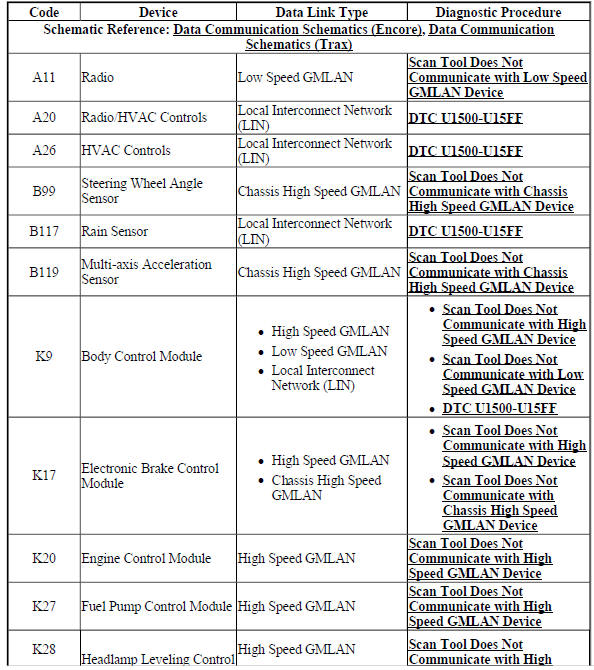
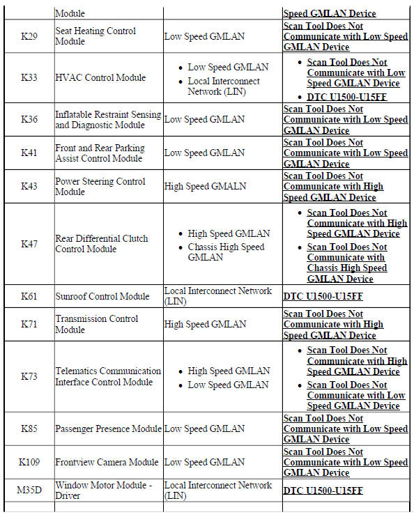
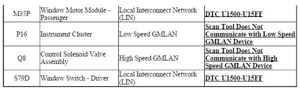
This table identifies which serial data link that a particular device uses for in-vehicle data transmission. Some devices may use more than one data link to communicate. Some devices may have multiple communication circuits passing through them without actively communicating on that data link. This table is used to assist in correcting a communication malfunction. Not all devices listed will be applicable to all vehicles. Refer to the schematics to determine which devices apply. For the description and operation of these serial data communication circuits, refer to Data Link Communications Description and Operation.
Data Link References
Repair instructions
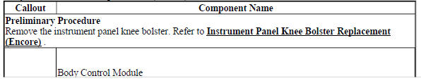
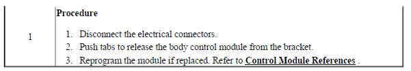
BODY CONTROL MODULE REPLACEMENT (ENCORE)
.gif)
Fig. 21: Body Control Module
Body Control Module Replacement (Encore)
BODY CONTROL MODULE REPLACEMENT (TRAX)
Fig. 22: Body Control Module
Body Control Module Replacement (Trax)
.jpg)
READ NEXT:
 Data communications - Description and operation
BODY CONTROL SYSTEM DESCRIPTION AND OPERATION
The body control system consists of the body control module (BCM),
communications, and various input and
outputs. Some inputs, outputs and messages requi
SEE MORE:
DTC B0091: Center front impact sensor
Diagnostic Instructions
Perform the Diagnostic System Check - Vehicle prior to using this
diagnostic procedure.
Review Strategy Based Diagnosis for an overview of the diagnostic
approach.
Diagnostic Procedure Instructions provides an overview of each
diagnostic category.
DTC Descriptors
D
Description and operation
SEAT BELT SYSTEM DESCRIPTION AND OPERATION
Seat Belt with P14 Block Diagram
Fig. 10: Seat Belt with P14 Block Diagram
Restraint System
NOTE: If the vehicle has been in a collision, refer to Repairs and
Inspections Required
After a Collision
The vehicle has front and rear seat belts that are the
