Chevrolet Trax: Rear hatch/gate description and operation
Liftgate Release System Components
- Body control module (BCM)
- Liftgate unlatch switch
- Liftgate latch assembly
- Liftgate unlatch relay
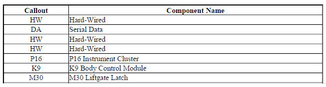
Liftgate Release Block Diagram
Fig. 44: Liftgate Release Block Diagram

Liftgate Release Operation
Liftgate Unlatch Switch
The BCM monitors supplies a 12 V signal to the liftgate unlatch switch so that when the switch is pressed, the voltage within the signal circuit is pulled low and in response, the BCM will detect the voltage drop and check the status of the door lock system. If the doors are locked, the BCM will ignore the request, if the All Doors Unlock has been commanded, the BCM will recognize the request and will provide voltage to the release relay.
Liftgate Latch Assembly
When BCM receives a liftgate release command from the liftgate unlatch switch, the BCM applies brief pulse of voltage to the liftgate unlatch relay control circuit, which energizes the coil side of the relay. The switch side of the liftgate unlatch relay then momentarily closes, supplying a brief pulse of battery positive voltage to the liftgate latch assembly. The liftgate latch assembly is continuously grounded and when it receives the voltage pulse, it will become energized and the latch will activate releasing the liftgate so that it may be manually raised to an open position.
Keyless Entry Transmitter
All doors of the vehicle must first be commanded to UNLOCK prior to pressing the liftgate unlatch switch. The BCM monitors the status of the vehicle door latches. If the passenger doors are locked, the BCM will ignore the signal from the liftgate unlatch switch. Pressing the appropriate button on the keyless entry transmitter will send a request to the remote control door lock receiver which will in turn send a serial data message to unlock all doors.
READ NEXT:
 Schematic wiring diagrams
SPECIFICATIONS
FASTENER TIGHTENING SPECIFICATIONS
Fastener Tightening Specifications
SCHEMATIC WIRING DIAGRAMS
WIPER/WASHER WIRINGSCHEMATICS (ENCORE)
Front Wiper/Washer Control and Wiper
Fig. 1: F
SEE MORE:
Rear Seats
The rear seats have head restraints
in the outboard seating positions
that can be lowered for better
visibility when the rear seat is
unoccupied.
To lower the head restraint, press
the button, located on the top of the
seatback, and push the head
restraint down.
When an occupant is in the seat,
alw
General Information
For service and parts needs, visit
your dealer. You will receive
genuine GM parts and GM-trained
and supported service people.
Genuine GM parts have one of
these marks:
California Proposition
65 Warning
Most motor vehicles, including this
one, contain and/or emit chemicals
known to the State of C
