Chevrolet Trax: Fuel injector circuit diagnosis
Diagnostic Instructions
- Perform the Diagnostic System Check - Vehicle prior to using this diagnostic procedure.
- Review Strategy Based Diagnosis for an overview of the diagnostic approach.
- Diagnostic Procedure Instructions provides an overview of each diagnostic category.
Diagnostic Fault Information
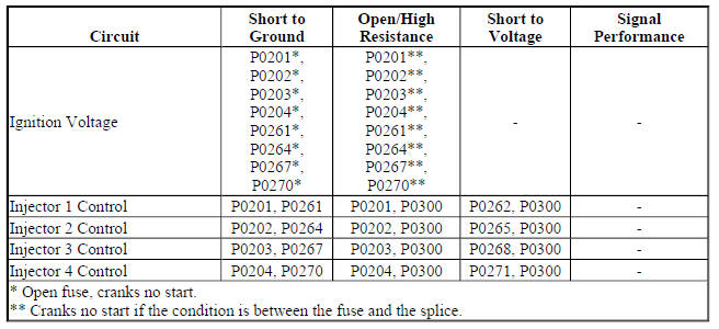
Circuit/System Description
The engine control module (ECM) enables the appropriate fuel injector pulse for each cylinder. Ignition voltage is supplied to the fuel injectors. The ECM controls each fuel injector by grounding the control circuit via a solid state device called a driver.
Reference Information
Schematic Reference
Engine Controls Schematics (Encore) , Engine Controls Schematics (Trax)
Connector End View Reference
WIRING SYSTEMS AND POWER MANAGEMENT - COMPONENT CONNECTOR END VIEWS - INDEX - ENCORE WIRING SYSTEMS AND POWER MANAGEMENT - COMPONENT CONNECTOR END VIEWS - INDEX - TRAX
Electrical Information Reference
- Circuit Testing
- Connector Repairs
- Testing for Intermittent Conditions and Poor Connections
- Wiring Repairs
Scan Tool Reference
Control Module References
Special Tool
CH 34730-2C Noid Light
Circuit/System Verification
- Engine cranking or running.
- Verify the scan tool parameters listed below do not display Malfunction.
- Cylinder 1-4 Injector Control Circuit Low Voltage Test Status
- Cylinder 1-4 Injector Control Circuit Open Test Status
- Cylinder 1-4 Injector Control Circuit High Voltage Test Status
- If Malfunction is displayed
Refer to Circuit/System Testing.
- If Malfunction is not displayed
- All OK.
Circuit/System Testing
- Ignition OFF, disconnect the harness connector at a Q17 Fuel Injector, ignition ON.
- Verify a test lamp illuminates between the ignition circuit terminal 1 and ground.
- If the test lamp does not illuminate and the circuit fuse is good
- Ignition OFF, remove the test lamp.
- Test for less than 2 ohms in the ignition circuit end to end.
- If 2 ohms or greater, repair the open/high resistance in the circuit.
- If less than 2 ohms, verify the fuse is not open and there is voltage at the fuse.
- If the test lamp does not illuminate and the circuit fuse is open
- Ignition OFF, remove the test lamp.
- Test for infinite resistance between the ignition circuit and ground.
- If less than infinite resistance, repair the short to ground on the circuit.
- If infinite resistance, test all components connected to the ignition voltage circuit for a short and replace as necessary.
- If the test lamp illuminates
- Verify that a test lamp does not illuminate between the ignition circuit 1 and the control circuit 2.
- If the test lamp illuminates
- Ignition OFF, remove the test lamp, disconnect the harness connector at the K20 Engine Control Module.
- Test for infinite resistance between the control circuit and ground.
- If less than infinite resistance, repair the short to ground on the circuit.
- If infinite resistance, replace the K20 Engine Control Module.
- If the test lamp does not illuminate
- Ignition OFF, connect the CH 34730-2C Noid Light to a fuel injector connector.
- Engine cranking.
- Verify the CH 34730-2C Noid Light turns ON and OFF for each fuel injector connector.
- If the CH 34730-2C is always OFF
- Ignition OFF, remove the CH 34730-2C Noid Light , disconnect the harness connector at the K20 Engine Control Module, ignition ON.
- Test for less than 1 V between the control circuit and ground.
- If 1 V or greater, repair the short to voltage on the circuit.
- If less than 1 V
- Ignition OFF.
- Test for less than 2 ohms in the control circuit end to end.
- If 2 ohms or greater, repair the open/high resistance in the circuit.
- If less than 2 ohms, replace the K20 Engine Control Module.
- If the CH 34730-2C is always ON
- Ignition OFF, remove the CH 34730-2C Noid Light , disconnect the harness connector at the K20 Engine Control Module.
- Test for infinite resistance between the control circuit and ground.
- If less than infinite resistance, repair the short to ground on the circuit.
- If infinite resistance, replace the K20 Engine Control Module.
- If the CH 34730-2C turns ON and OFF
- Test or replace the Q17 Fuel Injector.
Component Testing
Fuel Injector Diagnosis
Repair Instructions
Perform the Diagnostic Repair Verification after completing the repair.
- Fuel Injector Replacement
- Control Module References for Engine Control Module replacement, programming, and setup.
