Chevrolet Trax: DTC P182E OR P1915
Diagnostic Instructions
- Perform the Diagnostic System Check - Vehicle prior to using this diagnostic procedure.
- Review Strategy Based Diagnosis for an overview of the diagnostic approach.
- Diagnostic Procedure Instructions provides an overview of each diagnostic category.
DTC Descriptors
DTC P182E
Internal Mode Switch Indicates Invalid Range
DTC P1915
Internal Mode Switch Does Not Indicate Park/Neutral During Start
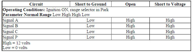
Diagnostic Fault Information
.jpg)
Typical Scan Tool Data
Internal Mode Switch A/B/C/P
Circuit/System Description
The manual shift detent lever with shaft position switch assembly, also known as the transmission internal mode switch assembly, is a sliding contact switch attached to the manual shift detent lever shaft inside the transmission. The 4 inputs to the transmission control module (TCM) from the switch indicate the position selected by the transmission manual shaft. The input voltage at the TCM is high when the switch is open and low when the switch is closed to ground. The state of each input is displayed on the scan tool TCM Internal Mode Switch A/B/C/P parameter. The Internal Mode Switch A/B/C/P parameter represents transmission range Signal A, Signal B, Signal C, and Signal P.
The park/neutral position switch is integrated into the transmission internal mode switch. The circuit uses the TCM as a pass-through connector only.
The park/neutral signal is sent from the park/neutral switch directly to the engine control module (ECM) and is used for engine start enable.
Conditions for Running the DTC
P182E
- DTC P0101, P0102, P0103, P0106, P0107, P0108, P0171, P0172, P0174, P0175, P0201, P0202, P0203, P0204, P0205, P0206, P0207, P0208, P0300, P0301, P0302, P0303, P0304, P0305, P0306, P0307, P0308, P0401, P042E, P0722, or P0723 is not set.
- Engine speed is 400-7,500 RPM for 5 s.
- Ignition voltage is 9-32 V.
- Engine torque signal is valid.
- DTC runs continuously when the above conditions are met.
P1915
- DTC P0722, P0723, or P1915 is not set.
- Transmission output shaft speed is 90 RPM or less.
- Ignition voltage is 6-32 V.
- DTC runs when conditions above are met during engine start sequence.
Conditions for Setting the DTC
P182E
Internal mode switch does not indicate a valid Park, Reverse, Neutral, or Drive Range position for 7 s.
P1915
Internal mode switch does not indicate Park or Neutral during the following sequence:
- Engine speed is less than 50 RPM for greater than 0.10 s.
- Engine speed is 50-480 RPM for greater than 0.07 s.
- Engine speed is greater than 500 RPM and the transmission input speed is greater than 100 RPM for greater than 1.25 s.
Action Taken When the DTC Sets
- P182E and P1915 are Type A DTCs.
- TCM commands maximum line pressure.
- TCM turns OFF all solenoids.
- TCM freezes transmission adaptive functions.
- TCM limits the transmission to reverse and 4th gear.
- TCM forces the torque converter clutch (TCC) OFF.
- TCM inhibits the Tap Up/Tap Down function.
- TCM inhibits neutral idle.
- TCM inhibits auto grade braking.
- TCM inhibits manual shifting of forward gears.
- TCM turns the high side driver OFF.
- TCM enables torque management.
Conditions for Clearing the DTC
P182E and P1915 are Type A DTCs.
Reference Information
Schematic Reference
Automatic Transmission Controls Schematics (Encore, MH8 or MHB) , Automatic Transmission Controls Schematics (Trax, MH8 or MHB)
Connector End View Reference
WIRING SYSTEMS AND POWER MANAGEMENT - COMPONENT CONNECTOR END VIEWS - INDEX - ENCORE WIRING SYSTEMS AND POWER MANAGEMENT - COMPONENT CONNECTOR END VIEWS - INDEX - TRAX
- Inline Harness Connector End Views (Encore) , Inline Harness Connector End Views (Trax)
Description and Operation
- Electronic Component Description
- Transmission Component and System Description
- Transmission General Description
Electrical Information Reference
- Circuit Testing
- Connector Repairs
- Testing for Intermittent Conditions and Poor Connections
- Wiring Repairs
DTC Type Reference
Powertrain Diagnostic Trouble Code (DTC) Type Definitions (LUV) , Powertrain Diagnostic Trouble Code (DTC) Type Definitions (2H0)
Scan Tool Reference
Control Module References for scan tool information
Special Tools
DT-48616-10 Adapter Harness
For equivalent regional tools, refer to Special Tools .
Circuit/System Verification
- Verify the range selector lever cable is adjusted properly. Refer to Range Selector Lever Cable Adjustment .
- If cable adjustment is not OK
Repair as necessary.
If cable adjustment is OK
- Ignition ON.
- Verify the scan tool TCM Internal Mode Switch A/B/C/P parameter matches the Transmission Internal Mode Switch Logic table for each transmission shift lever position.
If the parameter does not match
Refer to Circuit/System Testing.
If the parameter matches
- Verify the scan tool engine control module Park/Neutral Position Switch parameter displays Park/Neutral with the gear shift lever in Park or Neutral and In Gear in Reverse or Drive.
If Park/Neutral or In Gear is not displayed
Refer to Circuit/System Testing.
If Park/Neutral and In Gear is displayed
- Operate the vehicle within the Conditions for Running the DTC. You may also operate the vehicle within the conditions that you observed from the Freeze Frame/Failure Records data.
- Verify the DTC does not set.
If the DTC sets
Refer to Circuit/System Testing.
If the DTC does not set
- All OK.
Circuit/System Testing
NOTE: You must perform Circuit/System Verification first.
- Ignition OFF, remove the control valve body cover.
- Connect the vehicle harness connector to the Q8 Control Solenoid Valve Assembly.
- Disconnect the B15 Transmission Internal Mode Switch connector at the Q8 Control Solenoid Valve Assembly.
- Ignition ON.
- Verify the scan tool engine control module Park/Neutral Position Switch parameter displays In Gear.
If In Gear is not displayed
- Ignition OFF, disconnect the vehicle harness X1 connector at the Q8 Control Solenoid Valve Assembly.
- Install the DT-48616-10 adapter harness to the X1 connector at the Q8 Control Solenoid Valve Assembly.
- Test for infinite resistance between the DT-48616-10 adapter harness connector terminals 2 and 3.
- If less than infinite resistance, replace the Q8 Control Solenoid Valve Assembly.
- If infinite resistance.
- Disconnect the harness connector at the K20 Engine Control Module.
- Test for infinite resistance between the signal circuit and ground at the vehicle harness K20 Engine Control Module connector.
- If less than infinite resistance, repair the short to ground on the circuit.
- If infinite resistance, replace the K20 Engine Control Module.
If In Gear is displayed
- Verify the scan tool transmission control module Internal Mode Switch A/B/C/P parameter displays High High High High.
If High High High High is not displayed
Replace the Q8 Control Solenoid Valve Assembly.
If High High High High is displayed
- Install a 3 A fused jumper wire between the low reference circuit terminal F and each signal circuit listed below one at a time at the Q8 Control Solenoid Valve Assembly.
- Signal A - terminal B
- Signal B - terminal C
- Signal C - terminal D
- Signal P - terminal E
- Verify the scan tool transmission control module A/B/C/P parameter displays 1 Low and 3 High when a signal circuit is grounded.
If 1 Low and 3 High is not displayed
Replace the Q8 Control Solenoid Valve Assembly.
If 1 Low and 3 High is displayed
- Connect a 3-amp fused jumper wire between terminal A and terminal F.
- Verify the ECM Park/Neutral Position Switch parameter displays Park/Neutral.
If Park/Neutral is not displayed
- Ignition OFF, remove the jumper wire and disconnect the X1 connector at the Q8 Control Solenoid Valve Assembly.
- Install the DT-48616-10 adapter harness to the X1 connector at the Q8 Control Solenoid Valve Assembly.
- Test for less than 2 ohms between the adapter harness terminal 2 and the X2 connector terminal F at the Q8 Control Solenoid Valve Assembly.
- If greater than 2 ohms, replace the Q8 Control Solenoid Valve Assembly.
- If less than 2 ohms .
- Disconnect the connector at the K20 Engine Control Module.
- Test for less than 2 ohms in the vehicle harness park/neutral signal circuit, end to end.
- If 2 ohms or greater, repair the open/high resistance in the circuit.
- If less than 2 ohms, replace the K20 Engine Control Module.
- If Park/Neutral is displayed
- Replace the B15 Transmission Internal Mode Switch.
Repair Instructions
Perform the Diagnostic Repair Verification after completing the repair.
- Perform the Transmission Adaptive Values Learn following all transmission repairs.
- Control Valve Body Cover Replacement
- Manual Shift Detent Lever with Shaft Position Switch Assembly Replacement
- Range Selector Lever Cable Adjustment
- Control Module References - for Control Solenoid Valve Assembly or Engine Control Module replacement, programming and setup
DTC P1876
Diagnostic Instructions
- Perform the Diagnostic System Check - Vehicle prior to using this diagnostic procedure.
- Review Strategy Based Diagnosis for an overview of the diagnostic approach.
- Diagnostic Procedure Instructions provides an overview of each diagnostic category.
DTC Descriptor
READ NEXT:
 DTC P1876
Up and Down Shift Enable Switch Circuit Low Voltage
Circuit/System Description
When the shift lever is placed in manual mode (M), the driver shift request ,
also known as the tap shift
function, is a
DTC P2714 OR P2715
Diagnostic Instructions
Perform the Diagnostic System Check - Vehicle prior to using this
diagnostic procedure.
Review Strategy Based Diagnosis for an overview of the diagnostic
approach.
Diag
DTC P2719-P2721
Diagnostic Instructions
Perform the Diagnostic System Check - Vehicle prior to using this
diagnostic procedure.
Review Strategy Based Diagnosis for an overview of the diagnostic
approach.
Diag
SEE MORE:
Radio controls malfunction (monochrome display)
Diagnostic Instructions
Perform the Diagnostic System Check - Vehicle prior to using this
diagnostic procedure.
Review Strategy Based Diagnosis for an overview of the diagnostic
approach.
Diagnostic Procedure Instructions provides an overview of each
diagnostic category.
Diagnostic Fault
Towing the Vehicle
Caution
Incorrectly towing a disabled
vehicle may cause damage. The
damage would not be covered by
the vehicle warranty.
Have the vehicle towed on a flatbed
car carrier or a wheel lift tow truck.
If a wheel lift tow truck is used, the
drive wheels cannot contact the
road while the vehicle is being
