Chevrolet Trax: DTC B3794, P0564, P0565, P0567, P0568, P056C, P0580, P0581, P155A-P155C, OR P162C: Cruise control malfunction
DIAGNOSTIC CODE INDEX
.jpg)
DTC B3794, P0564, P0565, P0567, P0568, P056C, P0580, P0581, P155A-P155C, OR P162C: CRUISE CONTROL MALFUNCTION
Diagnostic Instructions
- Perform the Diagnostic System Check - Vehicle prior to using this diagnostic procedure.
- Review Strategy Based Diagnosis for an overview of the diagnostic approach.
- Diagnostic Procedure Instructions provides an overview of each diagnostic category.
DTC Descriptors
DTC B3794 08
Cruise Control Function Request Circuit
DTC B3794 61
Cruise Control Function Request Circuit
DTC P0564
Cruise Control Multifunction Switch Circuit
DTC P0565
Cruise Control Switch Circuit
DTC P0567
Cruise Control Resume Switch Circuit
DTC P0568
Cruise Control Set Switch Circuit
DTC P056C
Cruise Control Cancel Switch Circuit
DTC P0580
Cruise Control Multifunction Switch Circuit Low Voltage
DTC P0581
Cruise Control Multifunction Switch Circuit High Voltage
DTC P155A
Cruise Control Switch State Undetermined
DTC P155B
Cruise Control Set/Coast Switch 2 Circuit
DTC P155C
Cruise Control Resume/Acceleration Switch 2 Circuit
DTC P162C
Vehicle Speed Limiting/Warning Switch Circuit
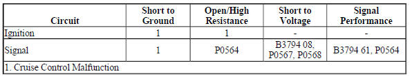
Diagnostic Fault Information
Circuit/System Description
The cruise control switch is an input to the body control module (BCM). The BCM monitors the cruise control on/off, set/coast, resume/accelerate and cancel switches via the cruise control switch signal circuit in order to detect when the driver has requested to perform a cruise control function. The BCM detects a specific voltage signal on the cruise control switch signal circuit when a switch is applied. The engine control module (ECM) receives the requested cruise control switch function from the BCM via a serial data message.
Conditions for Running the DTC
- The cruise switch is ON.
- The ignition is ON.
Conditions for Setting the DTC
B3794 08
The BCM detects an invalid voltage signal on the cruise control switch signal circuit for 1 second.
B3794 61
Stuck switch for either Resume/Accel or Set/Coast button for 60 seconds.
P0564, P0565, P0567, P0568, P056C
- The BCM detects an invalid voltage signal on the cruise control switch signal circuit for greater than 2 seconds and sends a serial data message to the ECM. The ECM sets these DTCs when the message is received.
- The ECM runs this diagnostic continuously.
P0580, P0581
- The ECM detects an invalid voltage signal on the cruise control switch signal circuit.
- The above condition is present for greater than 2 seconds.
- The ECM runs this diagnostic continuously.
P155A
The ECM is unable to determine the state of the cruise control switch.
P162C
The ECM is unable to determine the state of the vehicle speed limiting switch.
Actions Taken When the DTC Sets
B3794
- The malfunction indicator lamp (MIL) will not illuminate.
- The cruise control system is disabled.
P0564, P0565, P0567, P0568, P056C, P0580, P0581, P155A, P162C
DTCs P0564, P0565, P0567, P0568, P056C, P0580, P0581, P155A and P162C are type C DTCs
Conditions for Clearing the DTC
B3794
- The condition responsible for setting the DTC no longer exists.
- A history DTC will clear after 40 malfunction-free ignition cycles have occurred.
P0564, P0565, P0567, P0568, P056C, P0580, P0581, P155A, P162C
DTCs P0564, P0565, P0567, P0568, P056C, P0580, P0581, P155A and P162C are type C DTCs.
Reference Information
Schematic Reference
Cruise Control Schematics (Encore), Cruise Control Schematics (Trax)
Connector End View Reference
WIRING SYSTEMS AND POWER MANAGEMENT - COMPONENT CONNECTOR END VIEWS - INDEX - ENCORE WIRING SYSTEMS AND POWER MANAGEMENT - COMPONENT CONNECTOR END VIEWS - INDEX - TRAX
Description and Operation
Cruise Control Description and Operation
Electrical Information Reference
- Circuit Testing
- Connector Repairs
- Testing for Intermittent Conditions and Poor Connections
- Wiring Repairs
Scan Tool Reference
Control Module References for scan tool information
Circuit/System Verification
- Ignition ON.
- Verify the scan tool ECM Cruise Control Switch Status parameter changes between Off and On, Resume and Set when switching between each position on the cruise control switch.
If the parameter does not change
Refer to Circuit/System Testing.
If the parameter changes
- All OK.
Circuit/System Testing
NOTE:
- An open ignition circuit or fuse before the control module will cause communication DTCs or power mode mismatch DTCs to set against or in the control module. This failure mode will be diagnosed in the no communications diagnostic procedure or power mode mismatch.
- This test assumes the ignition circuit has a driver that will open under a high current condition before the fuse opens.
- The driver can open under normal conditions such as battery run down protection or a retained accessory power mode.
- Ignition OFF, disconnect the harness connector at the S70L Steering Wheel Controls Switch-Left, ignition ON.
- Verify a test lamp illuminates between the ignition circuit terminal 1 and ground.
If the test lamp does not illuminate
- Ignition OFF, disconnect the harness connector at the K9 Body Control Module.
- Test for greater than 100 ohms between the ignition circuit and ground.
- If 100 ohms or less, repair the short to ground on the circuit.
- If greater than 100 ohms
- Test for less than 2 ohms in the ignition circuit end to end.
- If 2 ohms or greater, repair the open/high resistance in the circuit.
- If less than 2 ohms, test or replace the K9 Body Control Module.
If the test lamp illuminates
- Verify the scan tool ECM Cruise Control Switch Status parameter is Off.
If not Off
- Ignition OFF, disconnect the harness connector at the K9 Body Control Module, ignition ON.
- Test for less than 1 V between the signal circuit terminal 3 and ground.
- If 1 V or greater, repair the short to voltage on the circuit.
- If less than 1 V, replace the K9 Body Control Module.
If Off
- Install a 3 A fused jumper wire between the signal circuit terminal 3 and the ignition circuit terminal 1.
- Verify the scan tool ECM Cruise Control parameter is Disabled.
If not Error
- Ignition OFF, disconnect the harness connector at the K9 Body Control Module.
- Test for infinite resistance between the signal circuit terminal 9 and ground.
- If less than infinite resistance, repair the short to ground on the circuit.
- If infinite resistance
- Test for less than 2 ohms in the signal circuit end to end.
- If 2 ohms or greater, repair the open/high resistance in the circuit.
- If less than 2 ohms, replace the K9 Body Control Module.
If Error
- Test or replace the S70L Steering Wheel Controls Switch-Left.
Repair Instructions
Perform the Diagnostic Repair Verification after completing the repair.
Control Module References for BCM replacement, programming and setup.
READ NEXT:
 DTC P0572 OR P0573: Brake switch
Diagnostic Instructions
Perform the Diagnostic System Check - Vehicle prior to using this
diagnostic procedure.
Review Strategy Based Diagnosis for an overview of the diagnostic
approach.
Diag
DTC P0575: Cruise control switch signal message counter
incorrect
Diagnostic Instructions
Perform the Diagnostic System Check - Vehicle prior to using this
diagnostic procedure.
Review Strategy Based Diagnosis for an overview of the diagnostic
approach.
Diag
Cruise control indicator malfunction
Diagnostic Instructions
Perform the Diagnostic System Check - Vehicle prior to using this
diagnostic procedure.
Review Strategy Based Diagnosis for an overview of the diagnostic
approach.
Diag
SEE MORE:
Headlamp switch replacement (encore)
Fig. 5: Headlamp Switch
Headlamp Switch Replacement (Encore)
HEADLAMP SWITCH REPLACEMENT (TRAX)
Fig. 6: Headlamp Switch
Headlamp Switch Replacement (Trax)
HAZARD WARNING SWITCH REPLACEMENT (TRAX)
Fig. 7: Hazard Warning Switch
Hazard Warning Switch Replacement (Trax)
HAZARD WARNING AND AC
Hood rear weatherstrip replacement (encore)
Fig. 41: Hood Rear Weatherstrip
Hood Rear Weatherstrip Replacement (Encore)
LIFTGATE STRUT REPLACEMENT
Fig. 42: Liftgate Strut
Liftgate Strut Replacement
FRONT OR REAR SIDE DOOR LOWER WEATHERSTRIP REPLACEMENT
Fig. 43: Side Door Lower Weatherstrip
Front or Rear Side Door Lower Weatherstri
