Chevrolet Trax: Crankshaft position sensor replacement
.gif)
Fig. 101: Crankshaft Position Sensor
Crankshaft Position Sensor Replacement


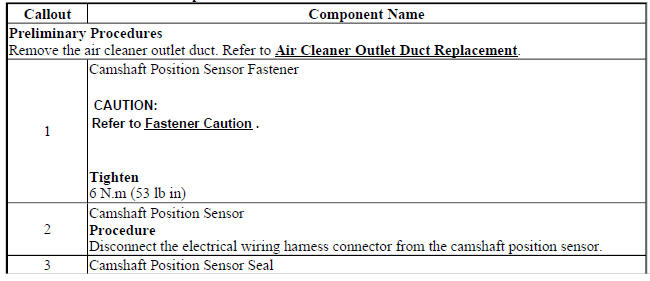
CAMSHAFT POSITION SENSOR REPLACEMENT
.gif)
Fig. 102: Camshaft Position Sensor
Camshaft Position Sensor Replacement
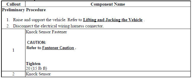
KNOCK SENSOR REPLACEMENT
.gif)
Fig. 103: Knock Sensor
Knock Sensor Replacement
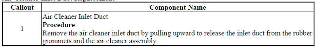
AIR CLEANER INLET DUCT REPLACEMENT
.gif)
Fig. 104: Air Cleaner Inlet Duct
Air Cleaner Inlet Duct Replacement
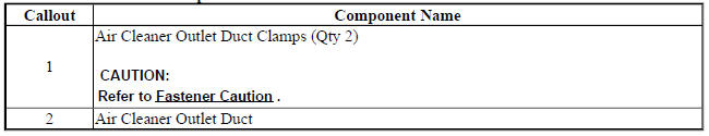
AIR CLEANER OUTLET DUCT REPLACEMENT
.gif)
Fig. 105: Air Cleaner Outlet Duct
Air Cleaner Outlet Duct Replacement
AIR CLEANER ELEMENT REPLACEMENT
.gif)
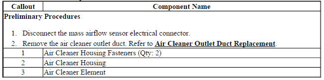
Fig. 106: Air Cleaner Element
Air Cleaner Element Replacement
AIR CLEANER ASSEMBLY REPLACEMENT
.gif)
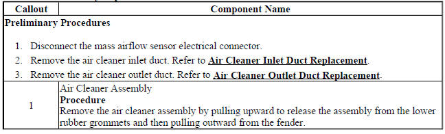
Fig. 107: Air Cleaner Assembly
Air Cleaner Assembly Replacement
CHARGE AIR COOLER REPLACEMENT
.gif)
Fig. 108: Charge Air Cooler
Charge Air Cooler Replacement
.jpg)
.jpg)
READ NEXT:
 Charge air cooler inlet air hose replacement
Removal Procedure
Remove the front bumper fascia. Refer to Front Bumper Fascia Replacement
(Trax) , Front Bumper
Fascia Replacement (Encore)
Fig. 109: Charge Air Cooler Inlet Air Hose Clamp
Schematic wiring diagrams
ENGINE CONTROLS WIRING SCHEMATICS (ENCORE)
Module Power, Ground, Serial Data, and MIL
Fig. 1: Module Power, Ground, Serial Data, and MIL
5V1, 5V2, and Low Reference Bus (1 of 2)
Fig. 2: 5V1, 5V2,
SEE MORE:
Front floor console wiring harness replacement (encore)
Fig. 120: Front Floor Console Wiring Harness
Front Floor Console Wiring Harness Replacement (Encore)
FRONT FLOOR CONSOLE WIRING HARNESS REPLACEMENT (TRAX)
Fig. 121: Front Floor Console Wiring Harness
Front Floor Console Wiring Harness Replacement (Trax)
FRONT FLOOR CONSOLE STOWAGE TRAY REPLA
Cooling system description and operation
Engine Coolant Indicators
The instrument panel cluster (IPC) shows the engine temperature on the
temperature gauge. The value is
sent on the data communication line from engine control module (ECM). When
the coolant temperature is
more than 128ºC (262ºF) IPC receives a discrete input from
