Chevrolet Trax: Control valve body cover replacement
Removal Procedure
- Disconnect the battery negative cable. Refer to Battery Negative Cable Disconnection and Connection .
- Raise and support the vehicle. Refer to Lifting and Jacking the Vehicle .
- Remove the front bumper fascia opening lower cover. Refer to Front Bumper Fascia Opening Lower Cover Replacement (Trax) .
- Remove the left front wheel house liner. Refer to Front Wheelhouse Liner Replacement (Trax) , Front Wheelhouse Liner Replacement (Encore) .
- Drain the transmission fluid.
- Disconnect the transmission fluid cooler inlet pipe from the transmission. Refer to Transmission Fluid Cooler Inlet Pipe Replacement .
- Disconnect the transmission fluid cooler outlet pipe from the transmission Refer to Transmission Fluid Cooler Outlet Pipe Replacement .
.gif)
Fig. 34: Identifying Control Valve Body Transmission Control Module (TCM)
Electrical Connector
- Disconnect the control valve body transmission control module electrical connector (1), then unclip the wiring harness from the cover.
.gif)
Fig. 35: View Of Control Valve Body
- Remove the control valve body cover bolts (1).
- Remove the control valve body cover (2).
- Remove the control valve body cover gasket (3).
CAUTION: Support the control solenoid valve assembly around the connector when removing the seal. Excessive pulling force can damage the internal electrical connections.
- Remove the control valve body cover wiring connector hole seal (4).
- Remove all traces of the old gasket material. Clean the transmission case and control valve body cover gasket surfaces.
Installation Procedure
.gif)
Fig. 36: View Of Control Valve Body
- Install the control valve body cover wiring connector hole seal (4).
- Install the control valve body cover gasket (3) to the control valve body cover.
- Install the control valve body cover (2).
- Hand start the control valve body cover bolts (1).
.gif)
Fig. 37: Identifying Valve Body Cover Bolt Tightening Sequence
CAUTION: Refer to Fastener Caution .
NOTE: Install all control valve body cover bolts and studs by hand then torque all bolts and studs in sequence.
- Install the control valve body cover bolts. Tighten the bolts in sequence to 12 (106 lb in).
Fig. 38: Identifying Control Valve Body Transmission Control Module (TCM)
Electrical Connector
- Connect the control valve body transmission control module electrical connector (1), then clip the wiring harness to the cover.
- Raise the vehicle.
- Connect the transmission fluid cooler outlet pipe to the transmission Refer to Transmission Fluid Cooler Outlet Pipe Replacement .
- Connect the transmission fluid cooler inlet pipe to the transmission. Refer to Transmission Fluid Cooler Inlet Pipe Replacement .
- Install the left front wheel house liner. Refer to Front Wheelhouse Liner Replacement (Trax) , Front Wheelhouse Liner Replacement (Encore) .
- Install the front bumper fascia opening lower cover. Refer to Front Bumper Fascia Opening Lower Cover Replacement (Trax) .
- Fill the transmission with correct fluid.
- Check transmission fluid level. Refer to Transmission Fluid Level and Condition Check .
- Lower the vehicle.
- Connect the battery negative cable. Refer to Battery Negative Cable Disconnection and Connection .
- Check for leaks.
CONTROL VALVE BODY REPLACEMENT
.gif)
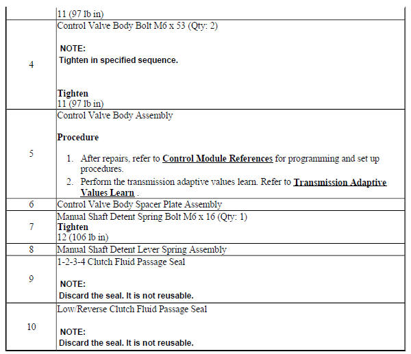
Fig. 39: View Of Control Valve Body
Control Valve Body Replacement
.jpg)
OUTPUT SPEED SENSOR REPLACEMENT
Fig. 40: Identifying Output Speed Sensor
Output Speed Sensor Replacement
.jpg)
INPUT SPEED SENSOR REPLACEMENT
Removal Procedure
- Remove the control valve body. Refer to Control Valve Body Replacement.
.gif)
Fig. 41: Identifying Input Speed Sensor Mounting Bolt
- Remove the input speed sensor bolt (2) M6 x 23.
- Unlock the 2 retaining tabs inside the transmission housing.
- Remove the input speed sensor (3).
- Remove the 3 input speed sensor seals (1).
Installation Procedure
Fig. 42: Identifying Input Speed Sensor Mounting Bolt
- Install the 3 input speed sensor seals (1).
- Install the input speed sensor (3).
- Verify that the retaining tabs are locked completely.
CAUTION: Refer to Fastener Caution .
- Install the input speed sensor bolt (2) M6 x 23 and tighten to 9 (80 lb in).
- Install the control valve body. Refer to Control Valve Body Replacement.
- Perform the transmission adaptive values learn procedure. Refer to Transmission Adaptive Values Learn .
