Chevrolet Trax Owners & Service Manuals

Chevrolet Trax: Air conditioning evaporator hose assembly replacement (LUJ, LUV)

Fig. 30: Air Conditioning Evaporator Hose Assembly

Air Conditioning Evaporator Hose Assembly Replacement (LUJ, LUV)
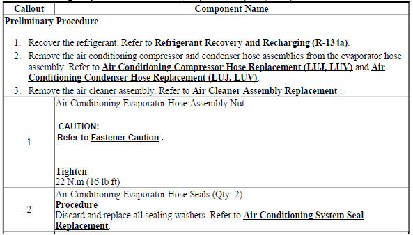
Air Conditioning Evaporator Hose Assembly Replacement (LUJ, LUV)

Air Conditioning Evaporator Hose Assembly Replacement (LUJ, LUV)

AIR CONDITIONING EVAPORATOR HOSE ASSEMBLY REPLACEMENT (2H0)

Fig. 31: Air Conditioning Evaporator Hose Assembly (2H0)

Air Conditioning Evaporator Hose Assembly Replacement (2H0)
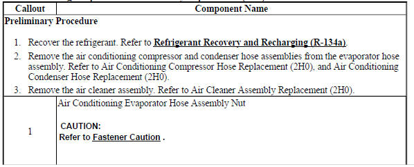
Air Conditioning Evaporator Hose Assembly Replacement (2H0)

Air Conditioning Evaporator Hose Assembly Replacement (2H0)

AIR CONDITIONING REFRIGERANT SERVICE VALVE CORE REPLACEMENT

Special Tools

  • GE 50078 Electronic Leak Detector
  • GE 46246 Valve Core Tool

For equivalent regional tools. Refer to Special Tools.

Removal Procedure

Fig. 32: Valve Core
Fig. 32: Valve Core

  1. Recover the refrigerant from the A/C system. Refer to Refrigerant Recovery and Recharging (R-134a).
  2. Using the GE 46246 Valve Core Tool , remove the valve core (1) from the service port.

Installation Procedure

Fig. 33: Valve Core
Fig. 33: Valve Core

CAUTION: Refer to Fastener Caution .

  1. Install the valve core (1) to the service port.
  2. Using the GE 46246 Valve Core Tool , tighten the valve core.
  3. Evacuate and recharge the A/C system. Refer to Refrigerant Recovery and Recharging (R-134a).
  4. Leak test the fittings of the component using GE 50078 Electronic Leak Detector.

AIR CONDITIONING REFRIGERANT DESICCANT REPLACEMENT (LUJ, LUV)

Fig. 34: Air Conditioning Refrigerant Desiccant

Air Conditioning Refrigerant Desiccant Replacement (LUJ, LUV)
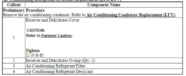
Air Conditioning Refrigerant Desiccant Replacement (LUJ, LUV)

AIR CONDITIONING REFRIGERANT DESICCANT REPLACEMENT (2H0)

Fig. 35: Air Conditioning Refrigerant Desiccant (2H0)

Air Conditioning Refrigerant Desiccant Replacement (2H0)
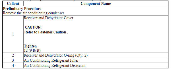
Air Conditioning Refrigerant Desiccant Replacement (2H0)

AIR CONDITIONING EVAPORATOR THERMAL EXPANSION VALVE REPLACEMENT (LUJ, LUV)

Fig. 36: Air Conditioning Evaporator Thermal Expansion Valve

Air Conditioning Evaporator Thermal Expansion Valve Replacement (LUJ, LUV)
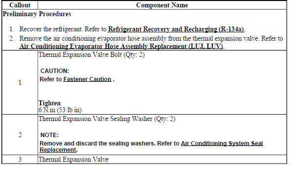
Air Conditioning Evaporator Thermal Expansion Valve Replacement (LUJ, LUV)

AIR CONDITIONING EVAPORATOR THERMAL EXPANSION VALVE REPLACEMENT (2H0)

Fig. 37: Air Conditioning Evaporator Thermal Expansion Valve (2H0)

Air Conditioning Evaporator Thermal Expansion Valve Replacement (2H0)

Air Conditioning Evaporator Thermal Expansion Valve Replacement (2H0)

Air Conditioning Evaporator Thermal Expansion Valve Replacement (2H0)

    READ NEXT:

     Air conditioning (a/c) refrigerant pressure sensor replacement (LUJ, LUV)

    Fig. 38: Air Conditioning (A/C) Refrigerant Pressure Sensor Air Conditioning (A/C) Refrigerant Pressure Sensor Replacement (LUJ, LUV) AIR CONDITIONING (A/C) REFRIGERANT PRESSURE SENSOR REPLACEME

     Heater and air conditioning evaporator and blower module removal and installation

    Removal Procedure Disconnect the negative battery cable. Refer to Battery Negative Cable Disconnection and Connection . Recover the refrigerant system. Refer to Refrigerant Recovery and Rechar

     Heater and air conditioning evaporator and blower upper case replacement

    Fig. 49: Heater And Air Conditioning Evaporator And Blower Upper Case Heater and Air Conditioning Evaporator and Blower Upper Case Replacement HEATER AND AIR CONDITIONING EVAPORATOR AND BLOWER LOW

    SEE MORE:

     Rear rail sectioning

    Removal Procedure WARNING: Refer to Approved Equipment for Collision Repair Warning . WARNING: Refer to Collision Sectioning Warning WARNING: Refer to Glass and Sheet Metal Handling Warning . Disable the SIR system. Refer to SIR Disabling and Enabling .  Disconnect the negative battery cable

     DTC P1876

    Up and Down Shift Enable Switch Circuit Low Voltage Circuit/System Description When the shift lever is placed in manual mode (M), the driver shift request , also known as the tap shift function, is activated. The driver shift request allows the vehicle operator to shift gears by pushing the plus (

    © 2019-2024 Copyright www.chevtrax.com