Chevrolet Trax: Sir service precautions
General Service Instructions
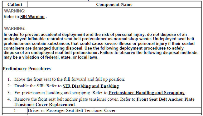
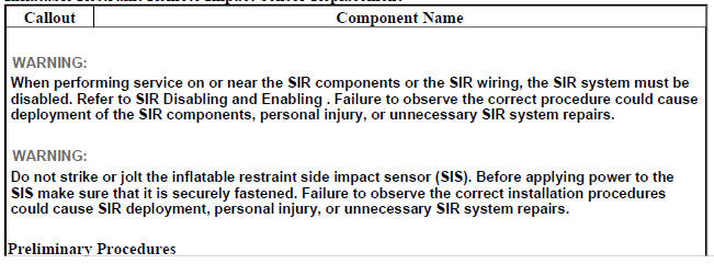
WARNING: When performing service on or near the SIR components or the SIR wiring, the SIR system must be disabled. Refer to SIR Disabling and Enabling . Failure to observe the correct procedure could cause deployment of the SIR components, personal injury, or unnecessary SIR system repairs.
NOTE: The Inflatable Restraint Sensing and Diagnostic Module (SDM) maintains a reserved energy supply. The reserved energy supply provides deployment power for the SIR air bags. Deployment power may be available for up to 2 minutes after disconnecting the vehicle power. Disabling the SIR system prevents deployment of the SIR air bags from the reserved energy supply.
NOTE: The following are general service instructions which must be followed in order to properly repair the vehicle and return it to its original integrity:
- Do not expose air bags to temperatures above 85 ºC (185 ºF)
- Verify the correct replacement part number. Do not substitute a component from a different vehicle
- Use only original GM replacement parts available from your authorized GM dealer. Do not use salvaged parts for repairs to the SIR system
NOTE: Discard any of the following components if it has been dropped from a height of 80 cm (15.75 in) or greater:
- Inflatable Restraint Sensing and Diagnostic Module
- Passenger instrument panel air bag
- Driver steering wheel air bag
- Driver steering wheel air bag coil
- Roof rail air bags
- Front and /or side impact sensors
- Seat belt achor and/or retractor pretensioners
- Front seat side air bag
- Knee air bag
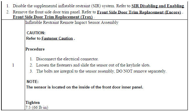
INFLATABLE RESTRAINT REMOTE IMPACT SENSOR REPLACEMENT
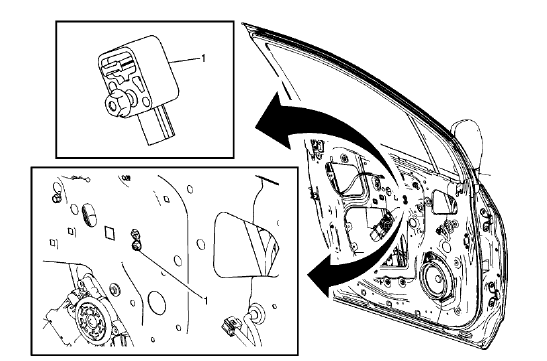
Fig. 10: Inflatable Restraint Remote Impact Sensor
Inflatable Restraint Remote Impact Sensor Replacement
FRONT END INFLATABLE RESTRAINT DISCRIMINATING SENSOR REPLACEMENT (TRAX)
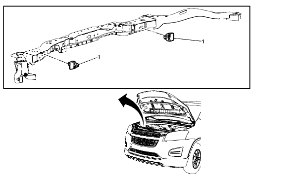
Fig. 11: Front End Inflatable Restraint Discriminating Sensor
Front End Inflatable Restraint Discriminating Sensor Replacement (Trax)
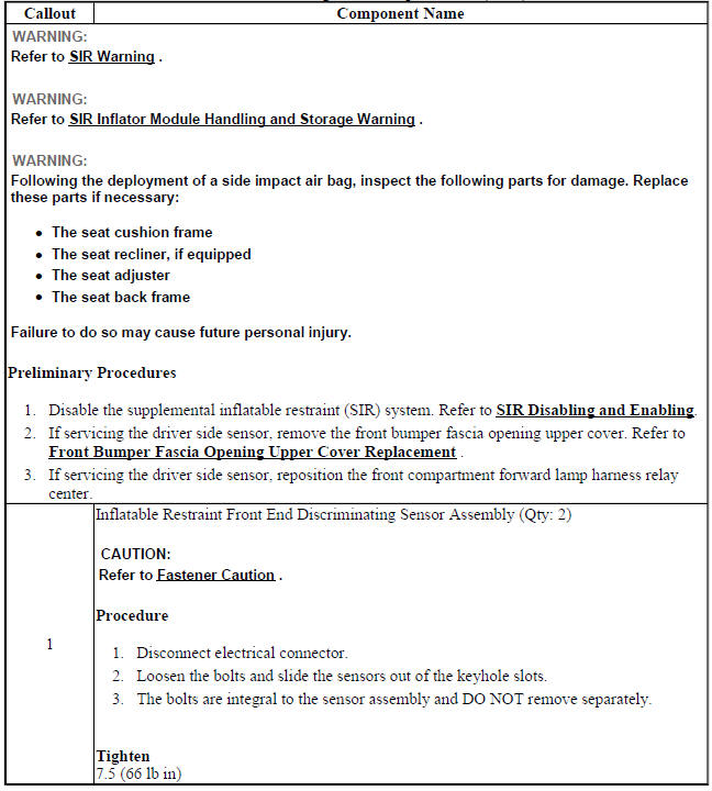
FRONT END INFLATABLE RESTRAINT DISCRIMINATING SENSOR REPLACEMENT(ENCORE)
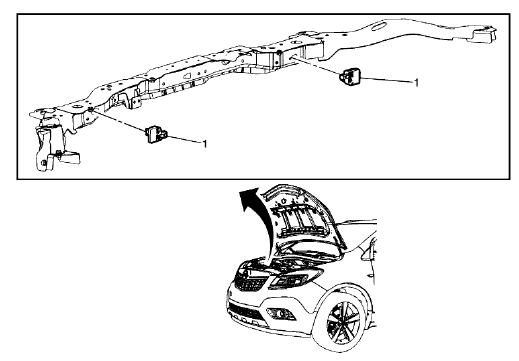
Fig. 12: Front End Inflatable Restraint Discriminating Sensor Replacement
(Encore)
Front End Inflatable Restraint Discriminating Sensor Replacement (Encore)
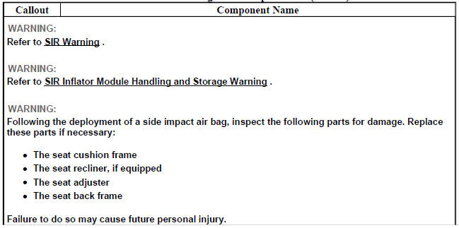
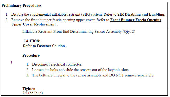
AIRBAG SIDE IMPACT SENSOR REPLACEMENT (ENCORE)
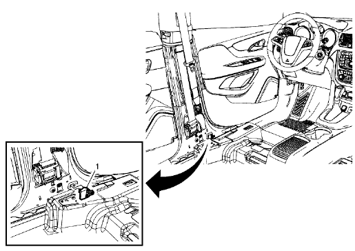
Fig. 13: Airbag Side Impact Sensor (Encore)
Airbag Side Impact Sensor Replacement (Encore)
.jpg)
AIRBAG SIDE IMPACT SENSOR REPLACEMENT (TRAX)
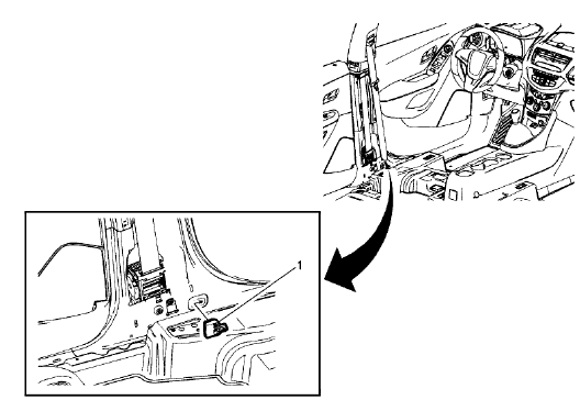
Fig. 14: Airbag Side Impact Sensor
Airbag Side Impact Sensor Replacement (Trax)
.jpg)
.jpg)
AIRBAG SENSING AND DIAGNOSTIC MODULE REPLACEMENT (ENCORE)
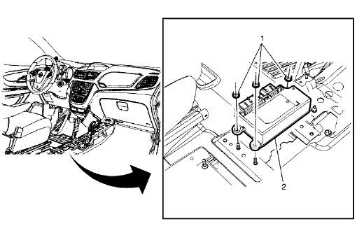
Fig. 15: Airbag Sensing and Diagnostic Module (Encore)
Airbag Sensing and Diagnostic Module Replacement (Encore)
.jpg)
AIRBAG SENSING AND DIAGNOSTIC MODULE REPLACEMENT (TRAX)
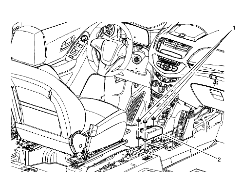
Fig. 16: Airbag Sensing and Diagnostic Module
Airbag Sensing and Diagnostic Module Replacement (Trax)
.jpg)
.jpg)
STEERING WHEEL AIRBAG REPLACEMENT (ENCORE)
.gif)
Fig. 17: Steering Wheel Airbag (Encore)
Steering Wheel Airbag Replacement (Encore)
.jpg)
.jpg)
STEERING WHEEL AIRBAG REPLACEMENT (TRAX)
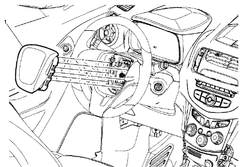
Fig. 18: Steering Wheel Airbag
Steering Wheel Airbag Replacement (Trax)
.jpg)
STEERING WHEEL AIRBAG COIL REPLACEMENT (TRAX)
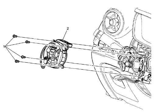
Fig. 19: Steering Wheel Airbag Coil
Steering Wheel Airbag Coil Replacement (Trax)
.jpg)
STEERING WHEEL AIRBAG COIL REPLACEMENT (ENCORE)
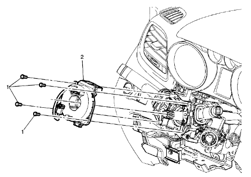
Fig. 20: Steering Wheel Airbag Coil (Encore)
Steering Wheel Airbag Coil Replacement (Encore)
.jpg)
.jpg)
AIRBAG STEERING WHEEL MODULE COIL CENTERING
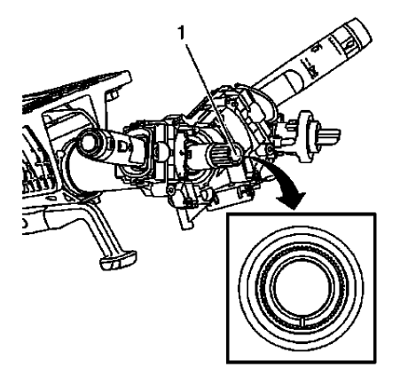
Fig. 21: Steering Shaft Centering Mark
CAUTION: The new SIR coil assembly will be centered. Improper alignment of the SIR coil assembly may damage the unit, causing an inflatable restraint malfunction.
- Verify the following conditions before centering the steering wheel inflatable restraint module coil:
- The wheels on the vehicle are straight ahead.
- The centering mark (1) of the steering shaft is in the 6 o'clock position
- Turn the lobe of the coil clockwise until the coil ribbon stops. Do not force.
- Turn the lobe of the coil counterclockwise approximately 3 turns to the Neutral position.
AIRBAG INSTRUMENT PANEL MODULE REPLACEMENT
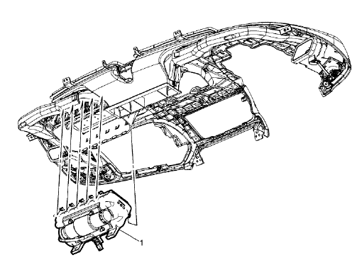
Fig. 22: Airbag Instrument Panel Module
Airbag Instrument Panel Module Replacement
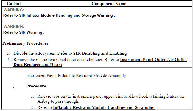

INSTRUMENT PANEL LOWER AIRBAG REPLACEMENT - DRIVER SIDE (AYF)
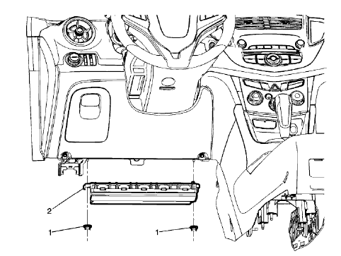
Fig. 23: Instrument Panel Lower Airbag - Driver Side
Instrument Panel Lower Airbag Replacement - Driver Side (AYF)
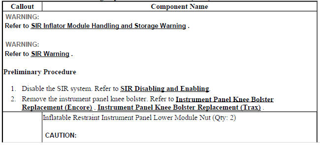
.jpg)
INSTRUMENT PANEL LOWER AIRBAG REPLACEMENT - PASSENGER SIDE (AYF)
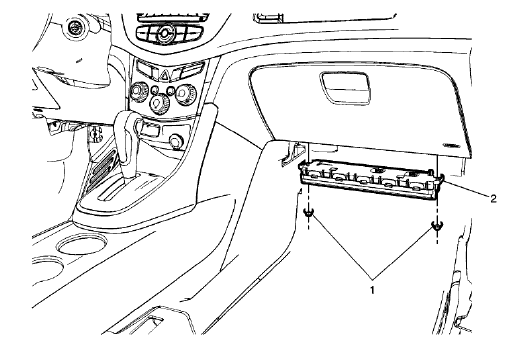
Fig. 24: Instrument Panel Lower Airbag - Passenger Side
Instrument Panel Lower Airbag Replacement - Passenger Side (AYF)
.jpg)
.jpg)
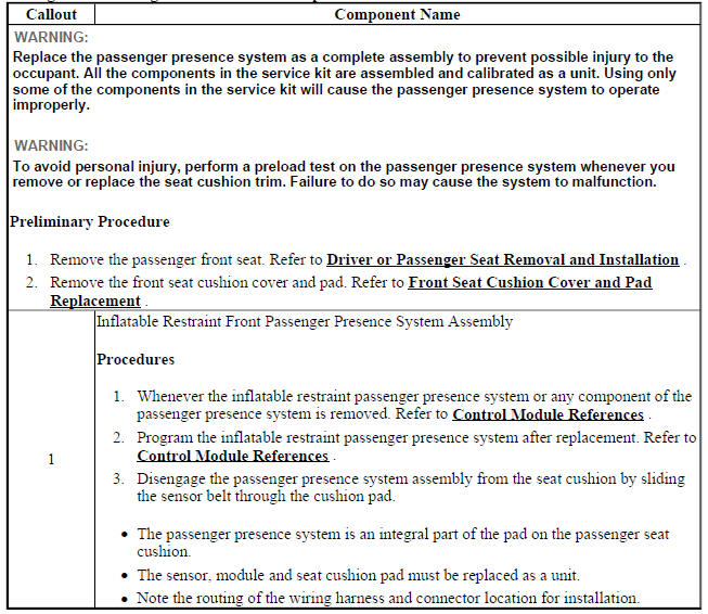
AIRBAG FRONT PASSENGER PRESENCE SENSOR REPLACEMENT
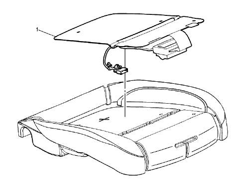
Fig. 25: Airbag Front Passenger Presence Sensor
Airbag Front Passenger Presence Sensor Replacement
FRONT SEAT OUTBOARD SEAT BACK AIRBAG REPLACEMENT
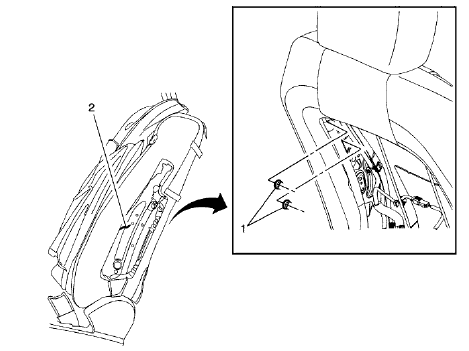
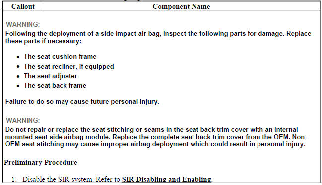
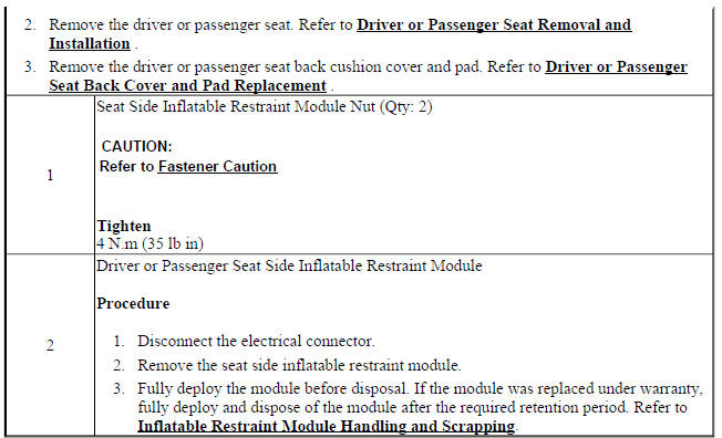
Fig. 26: Driver or Passenger Seat Side Inflatable Restraint Module & Nuts
Front Seat Outboard Seat Back Airbag Replacement
REAR SEAT BOLSTER AIRBAG REPLACEMENT (AYF)
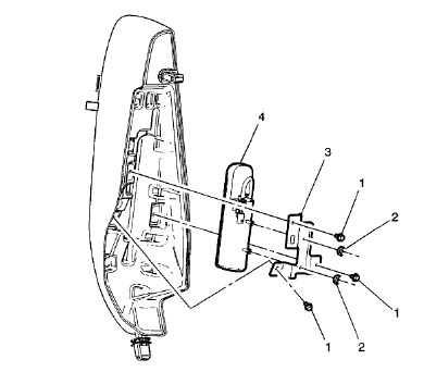
Fig. 27: Rear Seat Bolster Airbag
Rear Seat Bolster Airbag Replacement (AYF)
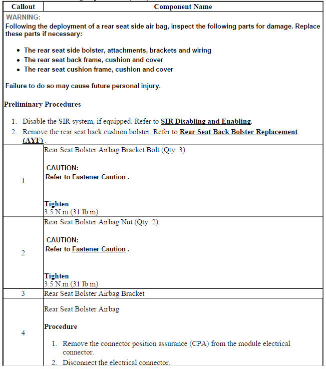

INSTRUMENT PANEL AIRBAG ARMING STATUS DISPLAY REPLACEMENT (TRAX)
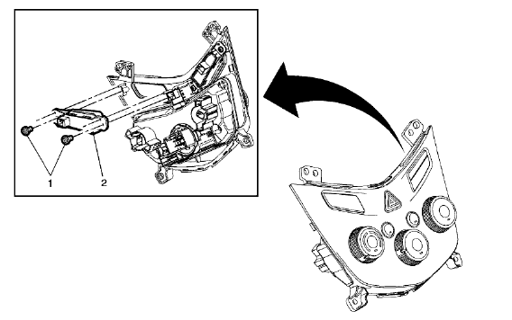
Fig. 28: Instrument Panel Airbag Arming Status Display
Instrument Panel Airbag Arming Status Display Replacement (Trax)

INSTRUMENT PANEL AIRBAG ARMING STATUS DISPLAY REPLACEMENT (ENCORE)
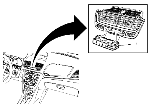
Fig. 29: Instrument Panel Airbag Arming Status Display
Instrument Panel Airbag Arming Status Display Replacement (Encore)

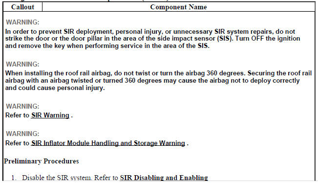
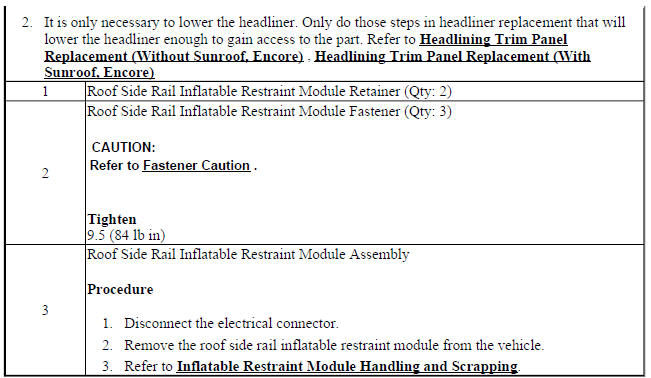
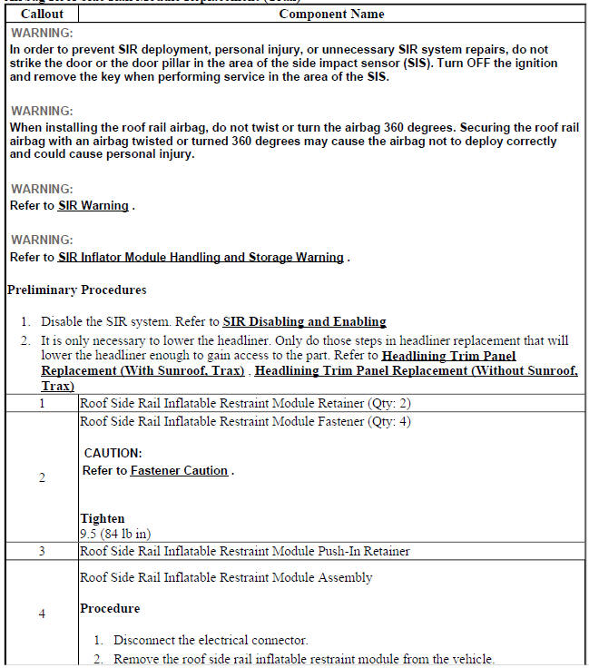
AIRBAG ROOF SIDE RAIL MODULE REPLACEMENT (ENCORE)
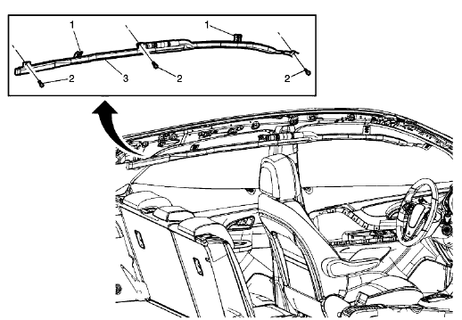
Fig. 30: Airbag Roof Side Rail Module
Airbag Roof Side Rail Module Replacement (Encore)
AIRBAG ROOF SIDE RAIL MODULE REPLACEMENT (TRAX)
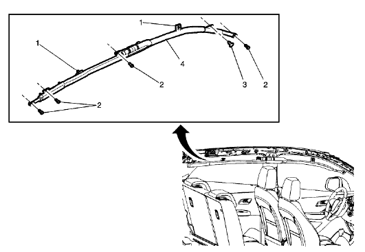
Fig. 31: Airbag Roof Side Rail Module
Airbag Roof Side Rail Module Replacement (Trax)

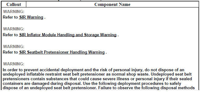
FRONT SEAT BELT RETRACTOR REPLACEMENT (WITH A69)
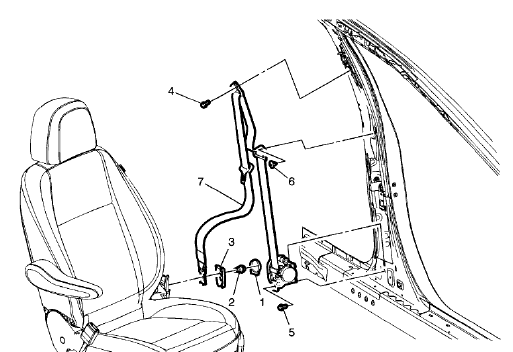
Fig. 32: Front Seat Belt Retractor (With A69)
Front Seat Belt Retractor Replacement (With A69)
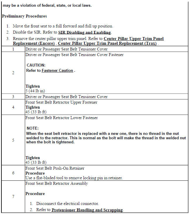
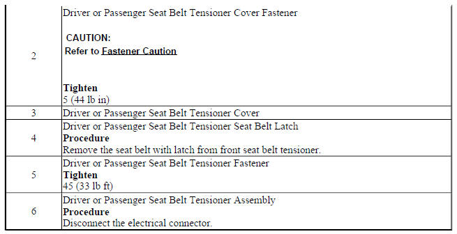
FRONT SEAT BELT ANCHOR PLATE TENSIONER REPLACEMENT
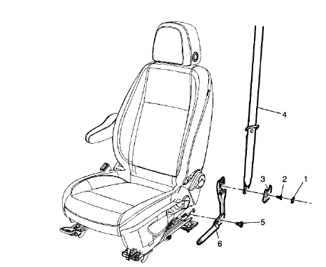
Fig. 33: Front Seat Belt Anchor Plate Tensioner
Front Seat Belt Anchor Plate Tensioner Replacement
