Chevrolet Trax: Schematic wiring diagrams
Automatic transmission controls wiring schematics (ENCORE, MH8 OR MHB)
Module Power, Ground, Data Communication, and MIL
.jpg)
Fig. 1: Module Power, Ground, Data Communication, and MIL
Speed and Temperature Sensors, Pressure and Shift Controls
.jpg)
Fig. 2: Speed and Temperature Sensors, Pressure and Shift Controls
Internal Mode Switch and Tap Up/Tap Down Switches
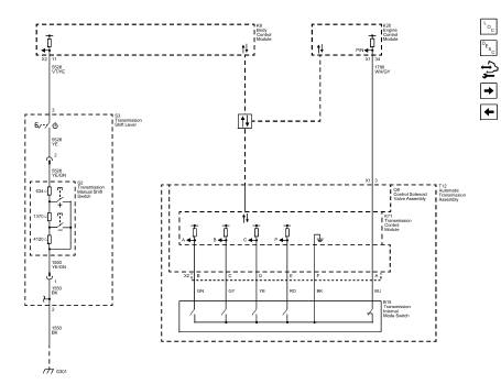
Fig. 3: Internal Mode Switch and Tap Up/Tap Down Switches
Shift Indicator
.jpg)
Fig. 4: Shift Indicator
AUTOMATIC TRANSMISSION CONTROLS SCHEMATICS (TRAX, MH8 OR MHB)
Module Power, Ground, Data Communication, and MIL
.jpg)
Fig. 5: Module Power, Ground, Data Communication, and MIL
Speed and Tempreature Sensors, Pressure and Shift Controls
.jpg)
Fig. 6: Speed and Tempreature Sensors, Pressure and Shift Controls
Internal Mode Switch and Tap Up/Tap Down Switches
.jpg)
Fig. 7: Internal Mode Switch and Tap Up/Tap Down Switches
Special tools and equipment
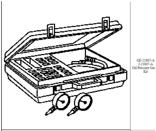
SPECIAL TOOLS
.jpg)
.jpg)
.jpg)
.jpg)
.jpg)
.jpg)
.jpg)
.jpg)
.jpg)
.jpg)
.jpg)
.jpg)
.jpg)
.jpg)
.jpg)
.jpg)
.jpg)
.jpg)
.jpg)
.jpg)
.jpg)
.jpg)
.jpg)
.jpg)
.jpg)
.jpg)
.jpg)
.jpg)
.jpg)
.jpg)
.jpg)
.jpg)
.jpg)
.jpg)
.jpg)
.jpg)
.jpg)
.jpg)
.jpg)
.jpg)
.jpg)
.jpg)
.jpg)
.jpg)
.jpg)
.jpg)
.jpg)
.jpg)
.jpg)
READ NEXT:
Throttle Positions
Engine Braking
A condition where the engine is used to slow the vehicle by manually
downshifting during a zero throttle
coastdown.
Full Throttle Downshift
A quick apply of the acce
The Hydra-matic 6T40/45/50 is a fully automatic, 6-speed, front-wheel drive,
electronic-controlled
transmission. It consists primarily of a 4-element torque converter, a compound
planetary gear set,
SEE MORE:
Diagnostic Instructions
Perform the Diagnostic System Check - Vehicle prior to using this
diagnostic procedure.
Review Strategy Based Diagnosis for an overview of the diagnostic
approach.
Diagnostic Procedure Instructions provides an overview of each
diagnostic category.
DTC Descriptors
D
Diagnostic Instructions
Perform the Diagnostic System Check - Vehicle prior to using this
diagnostic procedure.
Review Strategy Based Diagnosis for an overview of the diagnostic
approach.
Diagnostic Procedure Instructions provides an overview of each
diagnostic category.
DTC Descriptor
DT
