Chevrolet Trax: Fuel feed pipe replacement (AT TANK AWD)
.gif)
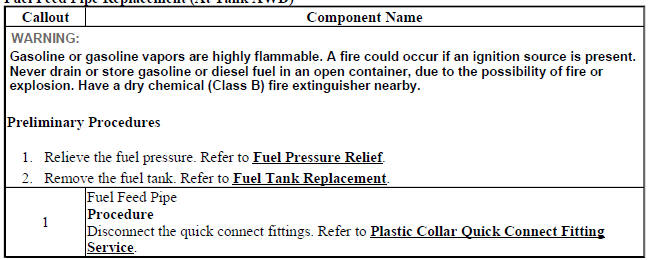
Fig. 27: Fuel Feed Pipe (At Tank - AWD)
Fuel Feed Pipe Replacement (At Tank AWD)
FUEL FEED PIPE REPLACEMENT (AT TANK FWD)
.gif)
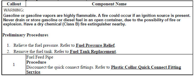
Fig. 28: Fuel Feed Pipe (At Tank - FWD)
Fuel Feed Pipe Replacement (At Tank FWD)
FUEL TANK FUEL PUMP MODULE REPLACEMENT (AWD)
Special Tools
CH-45722 Fuel Pump Locking Ring Wrench
For equivalent regional tools, refer to Special Tools (Diagnostic Tools) .
Removal Procedure
WARNING: Refer to Gasoline/Gasoline Vapors Warning .
WARNING: Always wear safety goggles when working with fuel in order to protect the eyes from fuel splash.
WARNING: Do not allow smoking or the use of open flames in the area where work on the fuel or EVAP system is taking place. Anytime work is being done on the fuel system, disconnect the negative battery cable, except for those tests where battery voltage is required.
- Remove the fuel tank. Refer to Fuel Tank Replacement.
- Remove the fuel sender assembly. Refer to Fuel Sender Assembly Replacement (AWD).
- Disconnect the electrical connector.
- Remove the fuel feed pipe. Refer to Fuel Feed Pipe Replacement (At Tank AWD).
- Remove the EVAP system hoses. Refer to Evaporative Emission System Hose/Pipe Replacement (Fuel Pump Module to Canister AWD), Evaporative Emission System Hose/Pipe Replacement (Canister to Pipe AWD).
.gif)
Fig. 29: Fuel Sender Lock Ring
- Install the CH-45722 Fuel Pump Locking Ring Wrench to the fuel pump module lock ring (1).
- Using the CH-45722 Fuel Pump Locking Ring Wrench and a long breaker-bar, rotate the fuel pump module lock ring (1) in a counterclockwise direction in order to unlock the lock ring from the fuel tank (2).
.gif)
Fig. 30: Fuel Tank Vent Pipe
- Raise the fuel pump module (2) enough to gain access to the fuel tank vent pipe (1) and disconnect the pipe from the fuel pump module. Refer to Plastic Collar Quick Connect Fitting Service.
.gif)
Fig. 31: Fuel Pump Module
- Remove the fuel tank fuel pump module (2).
- Remove and discard the fuel tank fuel pump module O-ring gasket (1).
Installation Procedure
.gif)
Fig. 32: Fuel Pump Module
- Install a NEW fuel tank fuel pump module O-ring gasket (1) to the fuel tank fuel pump module (2).
.gif)
Fig. 33: Fuel Tank Vent Pipe
- Lower the fuel pump module (2) into the fuel tank while connecting the fuel tank vent pipe (1) to the fuel pump module. Refer to Plastic Collar Quick Connect Fitting Service.
.gif)
Fig. 34: Fuel Sender Lock Ring
- Install the fuel tank fuel pump module lock ring (1) to the fuel tank (2).
- Using the CH-45722 Fuel Pump Locking Ring Wrench and a long breaker-bar, rotate the fuel pump module lock ring (1) in a clockwise direction in order to lock the lock ring.
- Install the EVAP system hoses. Refer to Evaporative Emission System Hose/Pipe Replacement (Fuel Pump Module to Canister AWD), Evaporative Emission System Hose/Pipe Replacement (Canister to Pipe AWD).
- Install the fuel feed pipe. Refer to Fuel Feed Pipe Replacement (At Tank AWD).
- Connect the electrical connector.
- Install the fuel sender assembly. Refer to Fuel Sender Assembly Replacement (AWD).
- Install the fuel tank. Refer to Fuel Tank Replacement.
READ NEXT:
 Fuel tank fuel pump module replacement (FWD)
Special Tools
CH-45722 Fuel Pump Locking Ring Wrench
For equivalent regional tools, refer to Special Tools (Diagnostic Tools) .
Removal Procedure
WARNING: Refer to Gasoline/Gasoline Vapors Warning .
W
Fuel tank pressure sensor replacement
Fig. 41: Fuel Tank Pressure Sensor (FWD)
Fuel Tank Pressure Sensor Replacement
FUEL SENDER ASSEMBLY REPLACEMENT (AWD)
Special Tools
EN-48482 Fuel Sender Lock Ring Wrench
Removal Procedure
WARNING:
Chassis control module replacement
Fig. 48: Fuel Pump Flow Control Module
Chassis Control Module Replacement
FUEL PUMP FLOW CONTROL MODULE REPLACEMENT
Fig. 49: Fuel Pump Flow Control Module
Fuel Pump Flow Control Module Replaceme
SEE MORE:
DTC B1529: Control module voltage reference output 5
Diagnostic Instructions
Perform the Diagnostic System Check - Vehicle prior to using this
diagnostic procedure.
Review Strategy Based Diagnosis for an overview of the diagnostic
approach.
Diagnostic Procedure Instructions provides an overview of each
diagnostic category.
DTC Descriptors
D
DTC P0667, P0668, OR P0669
Diagnostic Instructions
Perform the Diagnostic System Check - Vehicle prior to using this
diagnostic procedure.
Review Strategy Based Diagnosis for an overview of the diagnostic
approach.
Diagnostic Procedure Instructions provides an overview of each
diagnostic category.
DTC Descriptors
D
