Chevrolet Trax: Cylinder head replacement - Removal Procedure
Special Tools
- EN-470-B Angular Torque Wrench
- EN-955 Fixing Pin
- EN-953-A Fixing Tool
For equivalent regional tools, refer to Special Tools.
Removal Procedure
- Disconnect battery negative cable. Refer to Battery Negative Cable Disconnection and Connection .
- Remove the turbocharger. Refer to Turbocharger Replacement.
- Remove the intake manifold. Refer to Intake Manifold Replacement.
- Remove the water outlet. Refer to Water Outlet Replacement (LUJ, LUV) .
- Remove the camshaft position actuator solenoid valve intake and exhaust. Refer to Camshaft Position Actuator Solenoid Valve Replacement .
- Adjust the engine to TDC. Refer to Camshaft Timing Chain Inspection
.gif)
Fig. 72: Timing Chain Tensioner Plug
- Remove the timing chain tensioner plug (1) from the engine front cover.
.gif)
Fig. 73: Hexagonal Wrench Rotation Direction
NOTE: Remove and reinstall the EN-953-A fixing tool for this step.
- Install a wrench (1) on the cast hexagonal portion of the intake camshaft, rotate the camshaft toward the exhaust camshaft in order to apply tension.
.gif)
Fig. 74: Timing Chain Tensioner Bore And Pin
- Install EN-955 pin (2) to the timing chain tensioner bore (1) to secure it in place.
- Remove the wrench from intake camshaft.
.gif)
Fig. 75: Upper Timing Chain Guide And Bolts
- Remove the upper timing chain guide bolts (1).
- Remove the upper timing chain guide (2).
.gif)
Fig. 76: Intake Camshaft Sprocket Bolt And Hexagonal Wrench
- Loosen the intake camshaft sprocket bolt (2) while holding up the hexagon of the intake camshaft with a wrench (1).
- Loosen the exhaust camshaft sprocket bolt while holding up the hexagon of the exhaust camshaft with a wrench.

Fig. 77: Camshaft Position Exciter Wheels And Camshaft Sprocket Bolts
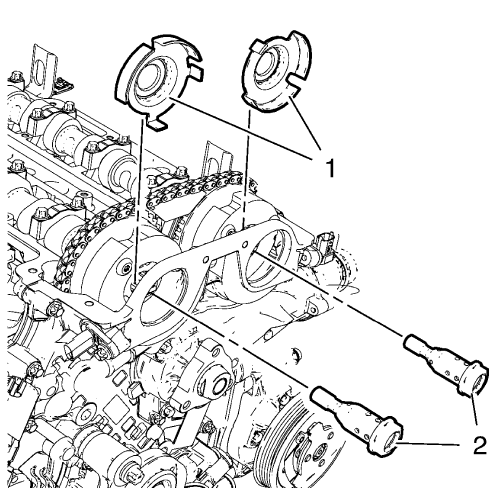
- Remove and DISCARD the camshaft sprocket bolts (2) and the camshaft position exciter wheels (1).
- Remove the both camshaft position sensors. Refer to Camshaft Position Sensor Replacement .
.gif)
Fig. 78: Timing Chain And Camshaft Sprockets
- Remove the camshaft sprockets (2) and timing chain (1) as one unit.
- Allow the camshaft sprockets (2) and timing chain (1) rest on the front cover. Do NOT remove sprockets or chain.
- Install the engine support fixture. Refer to Engine Support Fixture.
- Remove the engine mount bracket. Refer Engine Mount Bracket Replacement - Right Side.
- Remove the drive belt. Refer to Drive Belt Replacement.
- Remove the water pump pulley. Refer to Water Pump Pulley Replacement (LUJ, LUV) .
.gif)
Fig. 79: Engine Front Cover Bolts And Water Pump Bolts
- Remove 5 engine front cover bolts (1, 2).
- Remove 3 water pump bolts (3).
- Install engine mount bracket. Refer to Engine Mount Bracket Replacement - Right Side.
- Install engine mount. Refer to Engine Mount Replacement - Right Side.
- Remove engine support fixture. Refer Engine Support Fixture.
.gif)
Fig. 80: Cylinder Head Bolts Loosening Sequence
- Loosen the 12 cylinder head bolts in the sequence as shown above. Use the following procedure:
- First pass: Loosen the cylinder head bolts 90 degrees.
- Final pass: Loosen the cylinder head bolts 180 degrees.
.gif)
Fig. 81: Cylinder Head, Gasket, Bolts And Guide Sleeves
NOTE: Do not damage the guide sleeves (4, 5).
- Remove and DISCARD the 12 cylinder head bolts (1).
- With the aid of an assistant, lift the timing chain side of the cylinder head assembly slightly in direction of the transmission.
- Remove the cylinder head (2).
- Remove the cylinder head gasket (3) and discard the gasket.

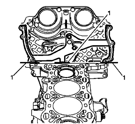
Fig. 82: Top Third Of Engine Front Cover Gasket
- With the cylinder head out of vehicle, bend the top third of the engine front cover gasket (1) back and forth until snaps off at the breaking point.
- Remove the assembly parts from cylinder head
- Remove the EN-953-A fixing tool
- Remove the intake camshaft. Refer to Intake Camshaft Removal.
- Remove the exhaust camshaft. Refer to Exhaust Camshaft Removal.
- Remove the hydraulic valve lash adjuster arms. Refer to Hydraulic Valve Lash Adjuster Arm Removal.
- Remove the hydraulic valve lash adjusters. Refer to Hydraulic Valve Lash Adjuster Removal.
- Remove the spark plug. Refer to Spark Plug Replacement .
- Remove the engine oil pressure indicator switch.
- Remove the timing chain tensioner. Refer to Timing Chain Tensioner Removal.
- Remove the 3 engine lift brackets.
- For disassembly of the cylinder head. Refer to Cylinder Head Disassemble.
- Clean and inspect the cylinder head. Refer to Cylinder Head Cleaning and Inspection.
- Transfer parts as necessary

