Chevrolet Trax: Component locator
DISASSEMBLED VIEWS
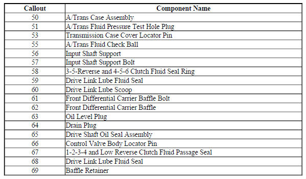
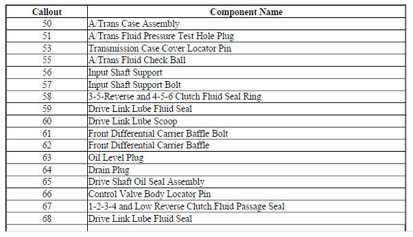
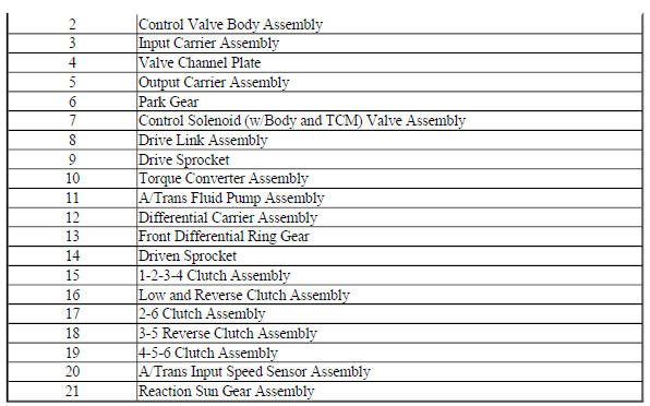
Case and Associated Parts
Fig. 1: Disassembled View Of Case & Associated Parts
Transmission Case Assembly - 6T30 - Gen 1
Fig. 2: Transmission Case Assembly -- 6T30 -- Gen 1
Transmission Case Assembly - 6T30 - Gen 2
Fig. 3: Transmission Case Assembly -- 6T30 -- Gen 2

Transmission Case Assembly - 6T40/6T45/6T50 - Gen 1
Fig. 4: View Of Transmission Case Assembly

Transmission Case Assembly - 6T40/6T45/6T50 - Gen 2
Fig. 5: Transmission Case Assembly Components -- 6T40/6T45/6T50 -- Gen 2
Torque Converter and Fluid Pump Housing Assembly- 6T30
Fig. 6: Torque Converter and Fluid Pump Housing Assembly -- 6T30
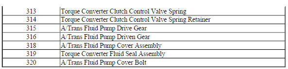
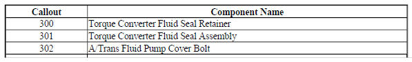
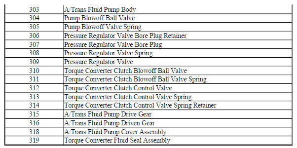
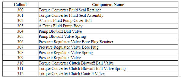
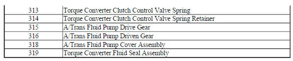
Torque Converter and Fluid Pump Housing Assembly- 6T40/6T45/6T50
Fig. 7: Torque Converter and Fluid Pump Housing Assembly Components --
6T40/6T45/6T50 -- Gen 2
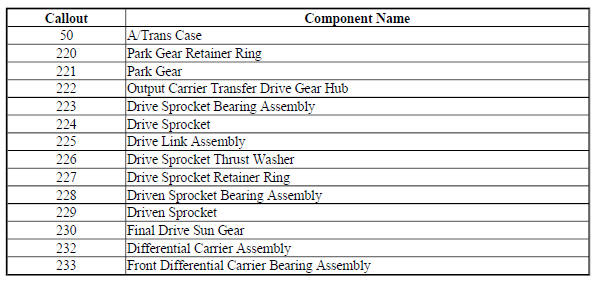
Drive Link Assembly
Fig. 8: Disassembled View Of Drive Link Assembly
Oil Pump Assembly- 6T30
Fig. 9: Oil Pump Assembly -- 6T30

Oil Pump Assembly- 6T40/6T45/6T50- Gen 1
Fig. 10: Disassembled View Of Oil Pump Assembly
Oil Pump Assembly- 6T40/6T45/6T50- Gen 2
Fig. 11: Oil Pump Assembly Components -- 6T40/6T45/6T50 -- Gen 2
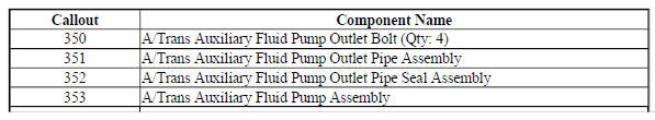
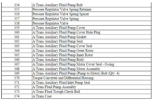
Auxiliary Fluid Pump and Hybrid Components - Hybrid Models
Fig. 12: Auxiliary Fluid Pump and Hybrid Components -- Hybrid Models
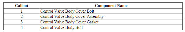
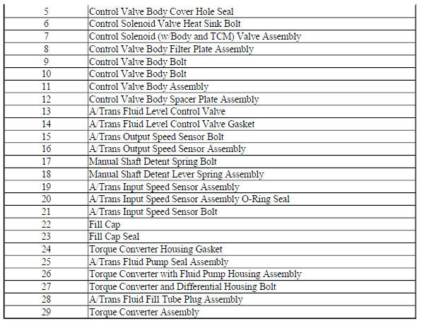
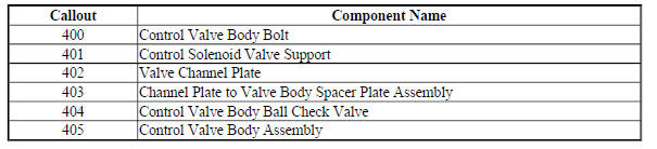
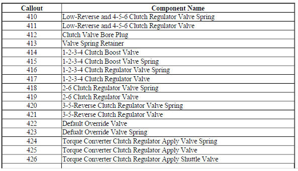
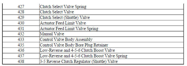
Control Valve Body Assembly (1 of 2 - Gen 1)
Fig. 13: View Of Control Valve Body Assembly (1 Of 2)
Control Valve Body Assembly (2 of 2 - Gen 1)
Fig. 14: View Of Control Valve Body Assembly (2 Of 2)
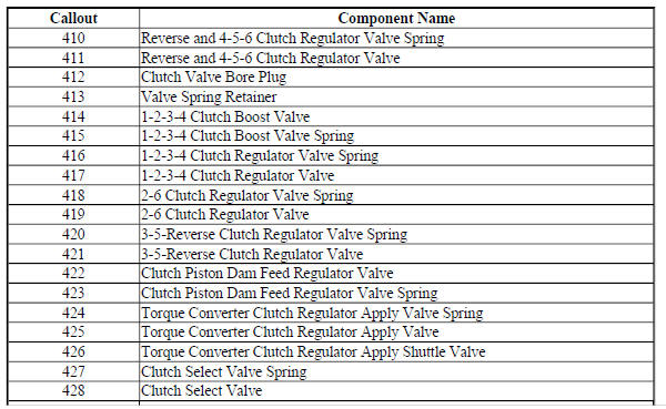
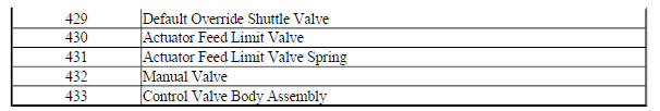
Control Valve Body Assembly (1 of 2 - Gen 2)
Fig. 15: Control Valve Body Assembly -- Gen 2 (1 Of 2)
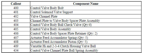
Control Valve Body Assembly (2 of 2 - Gen 2)
Fig. 16: Control Valve Body Assembly -- Gen 2 (2 Of 2)
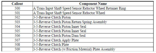
3-5 Reverse Clutch Assembly - Gen 1
Fig. 17: View Of 3-5 Reverse Clutch Assembly
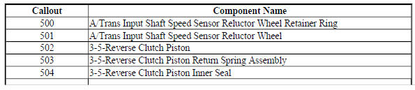
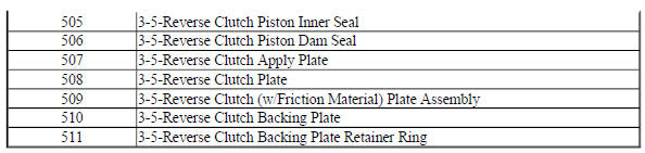
3-5 Reverse Clutch Assembly - Gen 2
Fig. 18: 3-5 Reverse Clutch Assembly Components - Gen 2

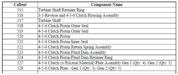
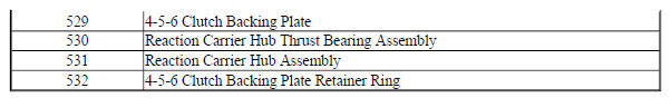
4-5-6 Clutch Assembly - Gen 1
Fig. 19: View Of 4-5-6 Clutch Assembly
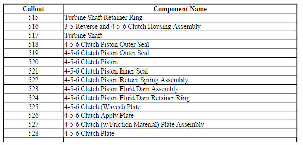
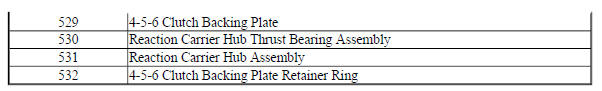
4-5-6 Clutch Assembly - Gen 2
Fig. 20: 4-5-6 Clutch Assembly Components -- Gen 2
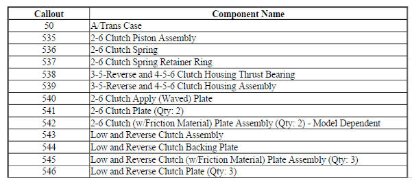
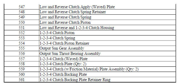
2-6, Low and Reverse and 1-2-3-4 Clutch Plate Assemblies - Gen 1
Fig. 21: Disassembled View Of 2-6, Low 7 Reverse & 1-2-3-4 Clutch Plate
Assemblies
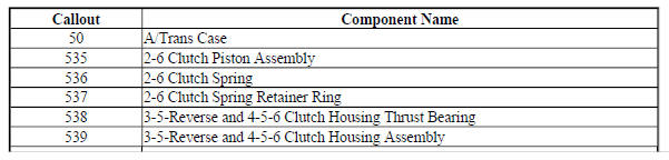
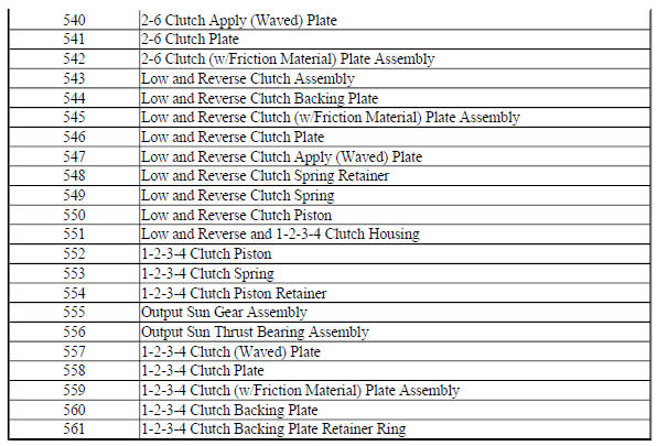
2-6, Low and Reverse and 1-2-3-4 Clutch Plate Assemblies - Gen 2
Fig. 22: 2-6, Low, Reverse And 1-2-3-4 Clutch Plate Assemblies - Gen 2
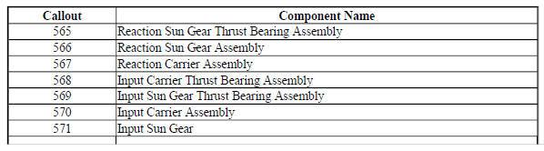
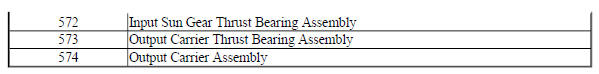
Input, Output and Reaction Gearsets- 6T30/6T40
Fig. 23: Input, Output and Reaction Gearsets -- 6T30/6T40
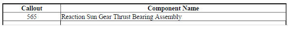
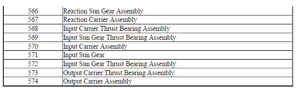
Input, Output and Reaction Gearsets- 6T45/6T50
Fig. 24: View Of Input, Output & Reaction Gearsets
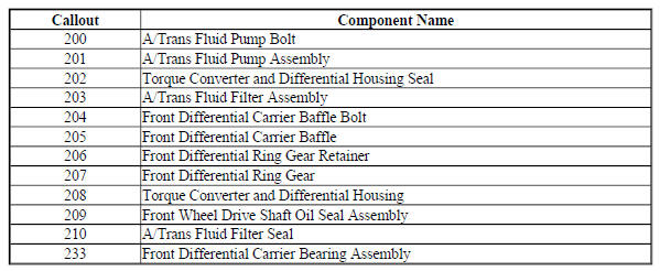
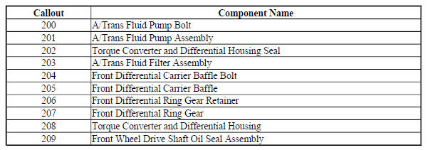
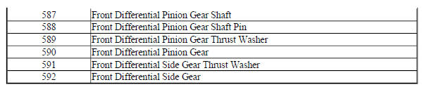
Front Differential Carrier Assembly (2 Pinion)
Fig. 25: Disassembled View Of Front Differential Carrier Assembly
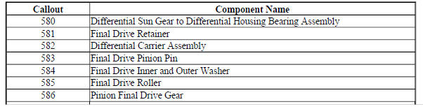
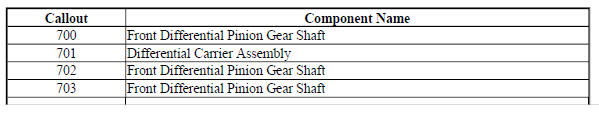
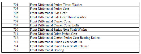
Front Differential Carrier Assembly (4 Pinion)
Fig. 26: Front Differential Carrier Assembly Components (4 Pinion)
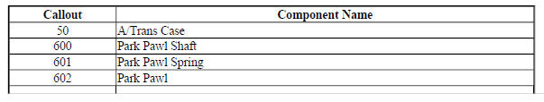
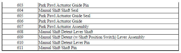
Park System Components
Fig. 27: View Of Park System Components
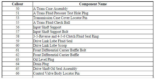
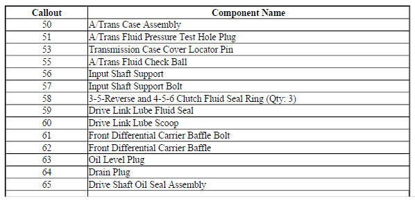
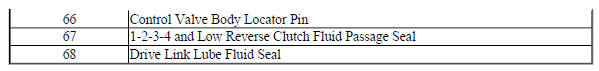
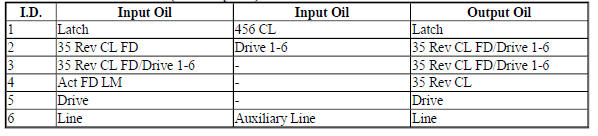
COMPONENT LOCATION
Fig. 28: Identifying Component Location

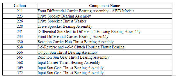
BUSHING, BEARING, AND WASHER LOCATIONS (GEN 2/HYBRID)
Fig. 29: Bushing, Bearing, and Washer Locations (Gen 2/Hybrid)

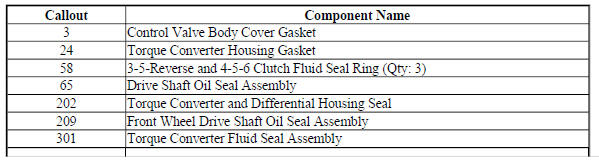
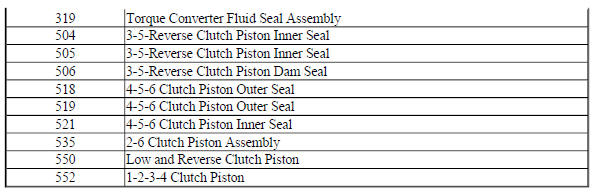
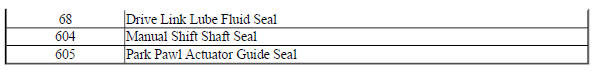
SEAL LOCATIONS (GEN 2/HYBRID)
Seal Locations (1 of 2)
Fig. 30: Seal Locations (Gen 2/Hybrid)
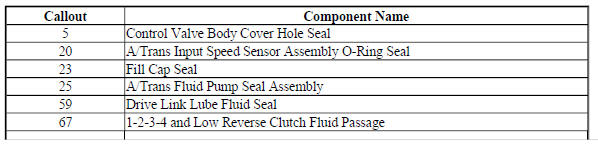
Seal Locations (2 of 2)
Fig. 31: Seal Locations (Gen 2/Hybrid)
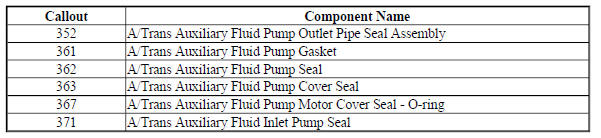
Auxiliary Fluid Pump and Hybrid Seals - Hybrid Models
Fig. 32: Auxiliary Fluid Pump and Hybrid Seals -- Hybrid Models
BALL CHECK VALVE LOCATIONS (GEN 2/HYBRID)
Fig. 33: Ball Check Valve Locations (Gen 2/Hybrid)
Ball Check Valve Locations (Gen 2/Hybrid)
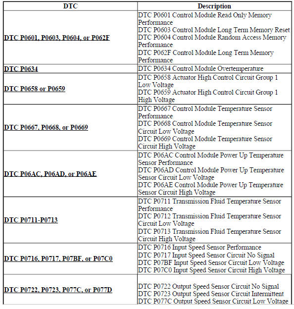
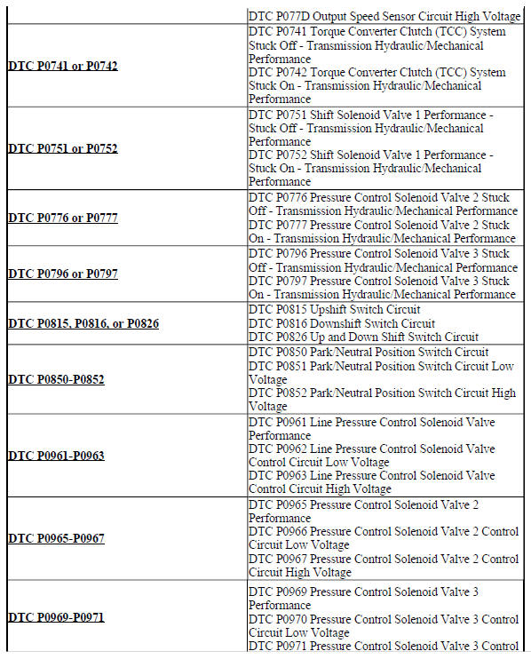
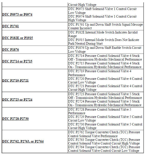
Diagnostic code index
DIAGNOSTIC CODE INDEX
READ NEXT:
 DTC P0601, P0603, P0604, OR P062F: Control module memory
Diagnostic Instructions
Perform the Diagnostic System Check - Vehicle prior to using this
diagnostic procedure.
Review Strategy Based Diagnosis for an overview of the diagnostic
approach.
Diag
DTC P0658 OR P0659
Diagnostic Instructions
Perform the Diagnostic System Check - Vehicle prior to using this
diagnostic procedure.
Review Strategy Based Diagnosis for an overview of the diagnostic
approach.
Diag
SEE MORE:
DTC B1925 OR B2170 (With memory A45): Seat cushion heater sensor
Diagnostic Instructions
Perform the Diagnostic System Check - Vehicle prior to using this
diagnostic procedure.
Review Strategy Based Diagnosis for an overview of the diagnostic
approach.
Diagnostic Procedure Instructions provides an overview of each
diagnostic category.
DTC Descriptors
D
Transfer case cleaning and inspection
Transfer Case Housing Cleaning and Inspection
Fig. 53: Transfer Case Housing Cleaning And Inspection Points
Transfer Case Cleaning and Inspection
Transfer Case Rear Extension Housing Cleaning and Inspection
Fig. 54: Transfer Case Rear Extension Housing Cleaning And Inspection Areas
Transfer
